Vector modulation – Atec Agilent-N5182A User Manual
Page 17
17
Vector Modulation
–200
–150
–100
–50
0
50
100
150
200
3
1
–1
–3
–5
–7
–9
–11
–13
–15
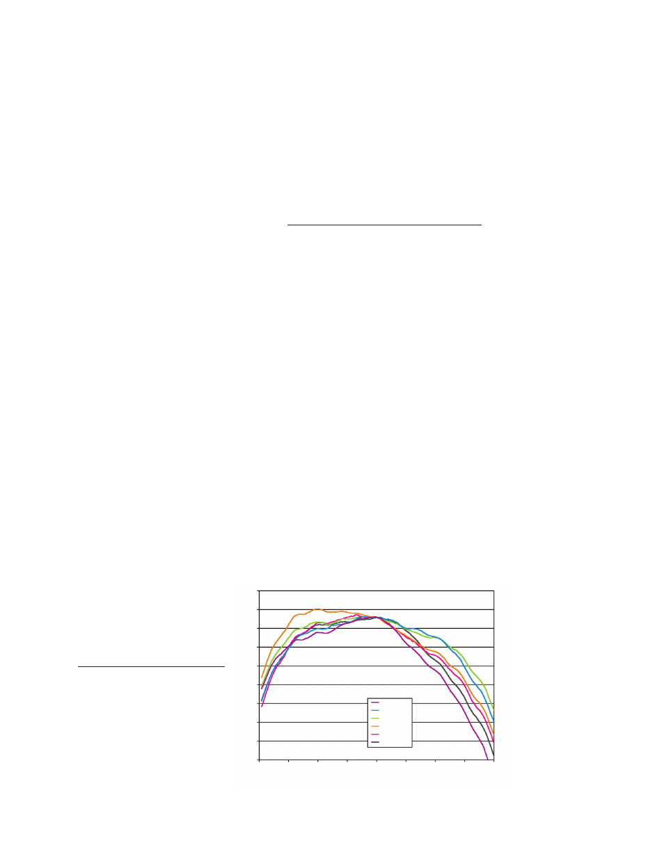
Frequency offset from carrier (MHz)
dB
5800 MHz
3500 MHz
2200 MHz
1900 MHz
1800 MHz
850 MHz
I/Q bandwidth using external I/Q source (ALC off)
I/Q input and output data
1
External I/Q inputs
2
Impedance
50 Ω (nom)
Bandwidth
Up to 100 MHz baseband (nom)
Up to 200 MHz RF (nom)
I offset
±100 mV
Q offset
±100 mV
Quadrature angle adjustment
±200 units
For optimum ACPR/EVM performance up to specified RF output power.
3
Range
I, Q (rms)
rss
100 kHz to 1.2 GHz
132 mV
187 mV
1.2 GHz to 1.45 GHz
123 mV
174 mV
1.45 GHz to 2.2 GHz
114 mV
161 mV
2.2 GHz to 2.45 GHz
100 mV
141 mV
2.45 GHz to 3.0 GHz
81 mV
115 mV
3.0 GHz to 3.9 GHz
112 mV
158 mV
3.9 GHz to 4.5 GHz
132 mV
187 mV
4.5 GHz to 5.8 GHz
90 mV
127 mV
5.8 GHz to 6 GHz
25 mV
35 mV
Internal I/Q from baseband generator
4
I offset
±20%
Q offset
±20%
I/Q gain
±1 dB
Quadrature angle adjustment
±10 °
I/Q phase
±360.00 °
I/Q skew
±800.00 ns
I/Q delay
±400.00 ns
I/Q delay resolution
1 picosecond
External I/Q outputs
Impedance
50 Ω (nom) per output
100 Ω (nom) differential output
Type
Single ended or differential (Option 1EL)
Maximum voltage per output
±2 V peak to peak; into high impedance
Bandwidth
50 MHz baseband (nom)
100 MHz RF (nom)
Common mode I/Q offset
±2.5 V into high impedance
Differential mode I offset
±25 mV into high impedance
Differential mode Q offset
±25 mV into high impedance
1. I/Q adjustments represent user
interface parameter ranges and not
“specifications.”
2. ALC must be on while using external IQ
inputs.
3. ACPR/EVM degrades beyond listed RF
output power.
4. Internal IQ adjustments apply to RF out
and IQ outputs simultaneously.