Input/output module (io), Vapor processor, Scada system – Franklin Fueling Systems TS 550 evo Fuel Management System Installation User Manual
Page 17: Generic device
17
Input/Output Module (IO)
The Low Voltage Input / Output Module is a non-intrinsically safe module that provides eight separate AC or DC voltage inputs
that can range from 0 to 240 volts. In addition to the AC / DC inputs, the IO module also includes four 4-20mA signal outputs.
IO Module Specifications
Number of Channels: 8 optically isolated inputs
4 analog outputs
Input Voltage Rating: 3 – 240 Volts AC or DC
(AC is rms value)
Input Current (each):
2 mA RMS
The AC / DC inputs are NOT dry contact inputs (there are 2 dry contact inputs on the power supply). Even though the
IO Module can accept AC line voltage levels, it is not intended to be used as a substitute for the AC Input Module for
dispenser hook inputs. Dispenser hook signals often have leakage currents that could cause false ‘on’ signals when used
with the IO Module.
Important: Use caution if both low voltage and high voltage signals are used simultaneously for the voltage
inputs. Use agency approved wire rated at 600V for safety and always make sure terminal connections
are tight and that no loose wire strands exist.
The IO Module’s four 4-20mA signal outputs can be used to interface to an external device such as a SCADA
(Supervisory Control And Data Acquisition) system or a building monitoring system. Typically, data such as tank levels or
line pressures can be sent via the 4-20 outputs.
Important: The IO Module supplies 4-20mA loop power. Do NOT connect it to an external device that supplies
loop power or use an external power supply for the loop. Doing so may damage the IO and/or the
external device. For similar reasons DO NOT connect the IO Module’s 4-20mA outputs to the 4-20mA
inputs of the 4-20mA Input Module. The 4-20mA Input Module is intrinsically safe and cannot be used
with the non-intrinsically safe IO Module; connecting the two together may damage either or both
modules.
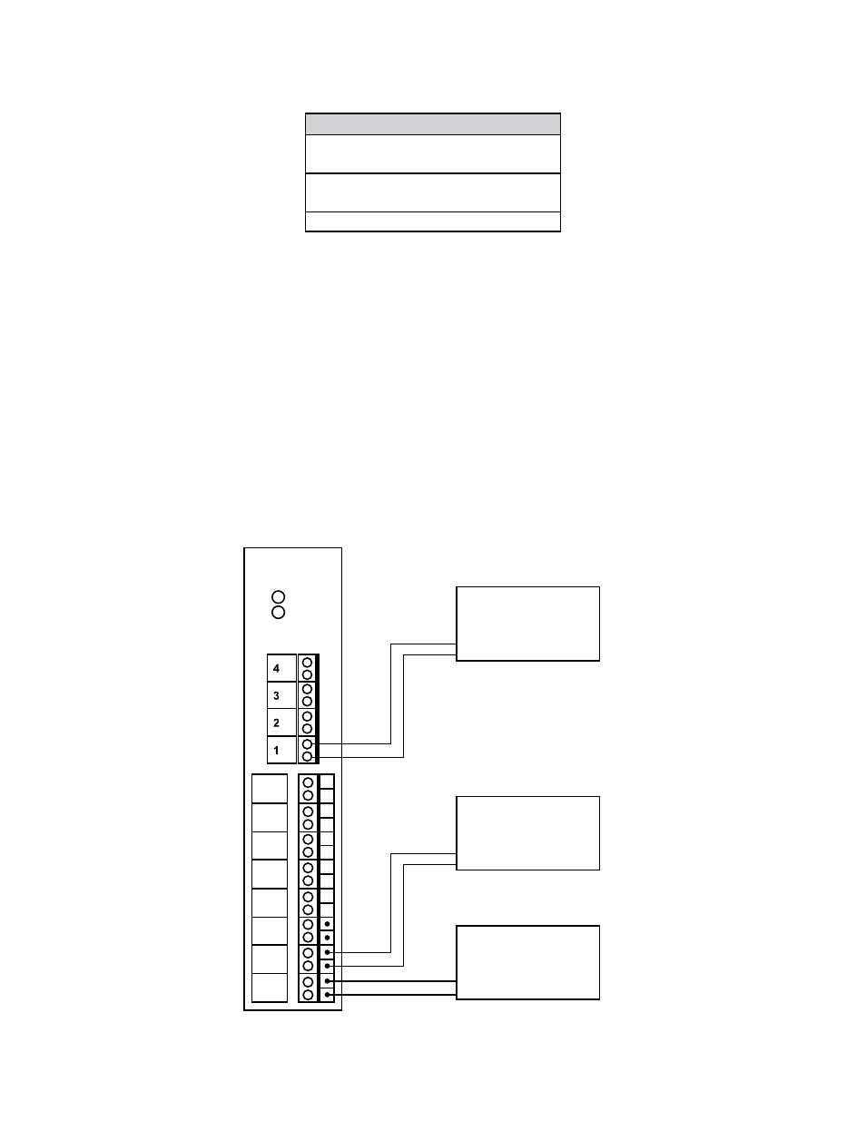
IO Module
RUN
ERR
Chan
3
Chan
2
Chan
1
Chan
6
Chan
5
Chan
4
Chan
8
Chan
7
Line
Neutral
Line
Neutral
Vapor Processor
(optional)
+
-
SCADA System
(optional)
Generic Device
(optional)
–
+
–
+
–
+
–
+
Figure 14: IO Module Wiring Schematic