Wiring the console & modules, Non-intrinsically safe module wiring – Franklin Fueling Systems TS 550 evo Fuel Management System Installation User Manual
Page 10
10
Wiring the Console & Modules
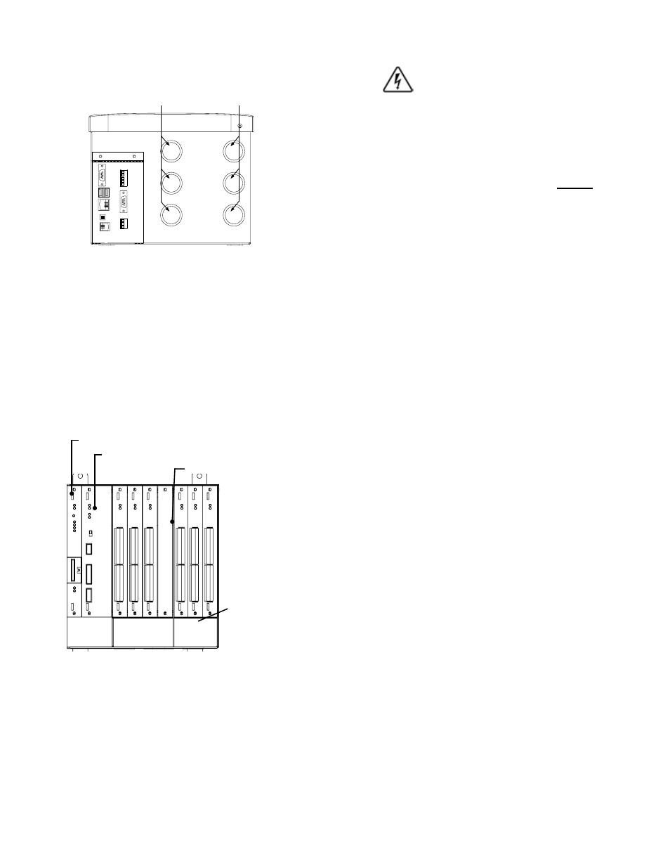
Conduit must only enter the console enclosure through the
designated knockouts as shown below in Figure
4.
COMM
2
BUS EX
T
CAN H
CAN L
GND
TPI RS-485
COMM
1
US
B
ETHERNET
HORN
FA
X/MODEM
NON-INTRINSICALLY SAFE WIRING ONLY!
FOR USE ONLY WITH EQUIPMENT SPECIFIED
IN THE INSTALLATION INSTRUCTIONS
(bottom view)
Intrinsically Safe
Knockouts
Non-Intrinsically
Safe Knockouts
Figure 3: TS-550 evo Conduit Knockouts
When installing additional modules, Franklin Fueling
Systems recommends installing non-IS modules from left
to right (from the open slot closest to the power supply)
and IS modules from right to left. In this scenario, all
unused slots will be concentrated in the middle of the
enclosure. This lets the IS barrier be easily moved and
allows for the possibility of adding future modules to the
system without needing to rewire those devices already
in place. It’s also a good idea to always start wiring your
module at the bottom-most set of channels (usually
Channel 1) to further future-proof your installation and
avoid any unnecessary confusion.
Non-IS Modules
(red)
Controller Module (CM)
Power Supply Module (PS)
Isolation Barrier
IS Modules (blue)
(front view with cover removed)
Figure 4: TS-550 evo Module Connections
It is important that intrinsically safe wiring only enter the
console through IS knockouts, and non-intrinsically safe
conduit only enter through non-IS knockouts. Maintain
the integrity of the intrinsically safe modules by keeping
probe and sensor wiring in conduit separate from all other
wiring. Probe and sensor wiring may be run in the same
conduit as long as they are both receiving power from the
same console and the wire complies with NEC 504.30 or
applicable local codes.
Non-Intrinsically Safe Module Wiring
Always lock out and tag electrical circuit
breakers while installing or servicing this
equipment and any related equipment. A
potentially lethal electrical shock hazard
and the possibility of an explosion or fire
from a spark can result if the electrical
circuit breakers are accidentally turned
on during installation or servicing.
Important: Non-intrinsically safe wiring cannot be
run in the same conduit as intrinsically
safe wiring. Conduit knockouts for IS and
non-IS module wiring are clearly identified
in Figure 7 for your reference. Non-IS
modules can be identified by their red
faceplates and should always be installed
to the left of the moveable isolation barrier.
Non-Intrinsically Safe modules include:
• Controller module
• Power Supply Module
• Relay Module
• AC Input Module
• Input / Output Module
• 10 Amp Relay Module
• 4-20mA EXP Analog Input Module
Danger