N-x144_iom_09 – Cla-Val X144 Technical Manual User Manual
Page 9
Section 2: Installation of the X144 e-FlowMeter (continued)
2.2 - Materials Required for Installation
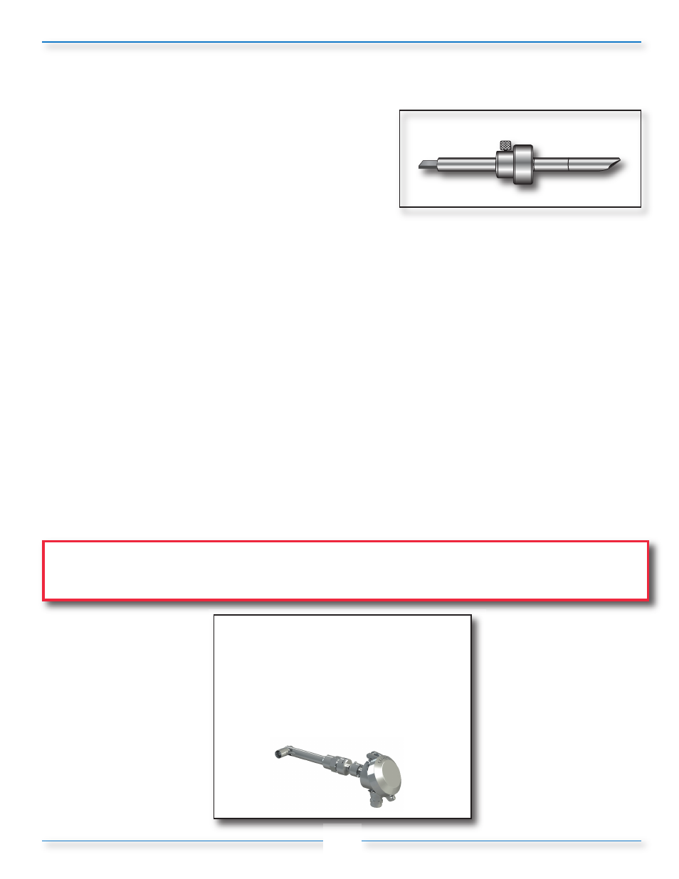
Insertion tool
•
Tool allows the proper installation and alignment of the
bluff body to be parallel to upstream flow, (Figure 1-5).
Power Supply
• 12/24 VDC, 0.7 Watts minimum. If more than one piece of equipment will be connected to
this power supply, you must verify that the power supply is large enough to handle all the power needs of
the entire system, not just the X144 e-FlowMeter.
• You will also need the appropriate equipment to connect the X144 to each the power supply. See your
local electrical specifications to determine the appropriate wire and connection hardware.
Pipe and Fittings Mounting Hardware
•
The X144 connects directly into the control valve on an inlet port and the size of the thread is dependent
on the specific valve size for which it it has been calibrated - no additional fittings are required.
Cabling
• The X144 has 30 feet cable supplied and attached as a factory standard. If additional lengths of cable are
needed, the connections should be made with #22 AWG or larger cable and may need to be shielded in
some environments where high electrical noise may exist. If using shielded cable, one end of the shielding
should be connected to an earth ground, such as a piping system fitting, etc.
CAUTION:
• In all cases, installation should be done by qualified mechanical or electrical personnel.
6
Figure 1-5: Insertion Tool
Log-on to
www.cla-val.com
and click on the
X144 e-FlowMeter icon to see
the installation video