N-x144_iom_27, X144 e-flowmeter, Quick start installation & removal instructions – Cla-Val X144 Technical Manual User Manual
Page 27
24
X144 e-FlowMeter
Quick Start Installation & Removal Instructions
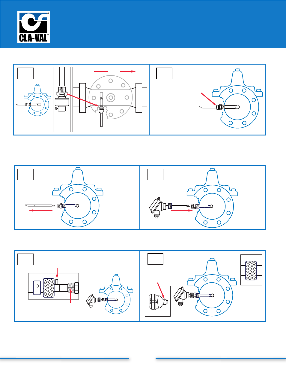
7
6
5
10
9
8
Step 5:
Insert straightened Swivel Insert/Measurement
Cylinder Assembly into valve, orient arrow on
wrench flat to point downstream
Step 6:
Loosen Thumb Set Screw. Remove Locking Collar
from tool. Remove tool and re-insert opposite end into
Swivel Assembly. Engage the tool and push firmly to orient
Measurement Cylinder 90˚ into flow path
Verify score mark is
flush with flat face
of straight thread
to ensure full
engagement
Step 7:
Remove tool from Threaded Swivel Insert
Step 8:
Insert tip of e-FlowMeter Sensor/Head Assembly
into Threaded Swivel Insert
Step 9:
Line-Up Centering Groove on straight threads
with Centering Pin; push to seat o-ring
Centering
Groove
Centering
Pin
Knurled
Lock
Step 10: HAND TIGHTEN
Knurled Lock onto straight
threads. Tighten Allen Set Screw with M3 Allen
Wrench to lock Sensor Head Assembly.
Proceed in accordance with Wiring Diagram
top view
inside view
flow
Allen Set
Screw
Step-By-Step X144 e-FlowMeter Installation Instructions (continued)