Cla-Val 61-02KO/661-02KO Valve User Manual
Deep well pump control valve
Deep Well Pump Control Valve
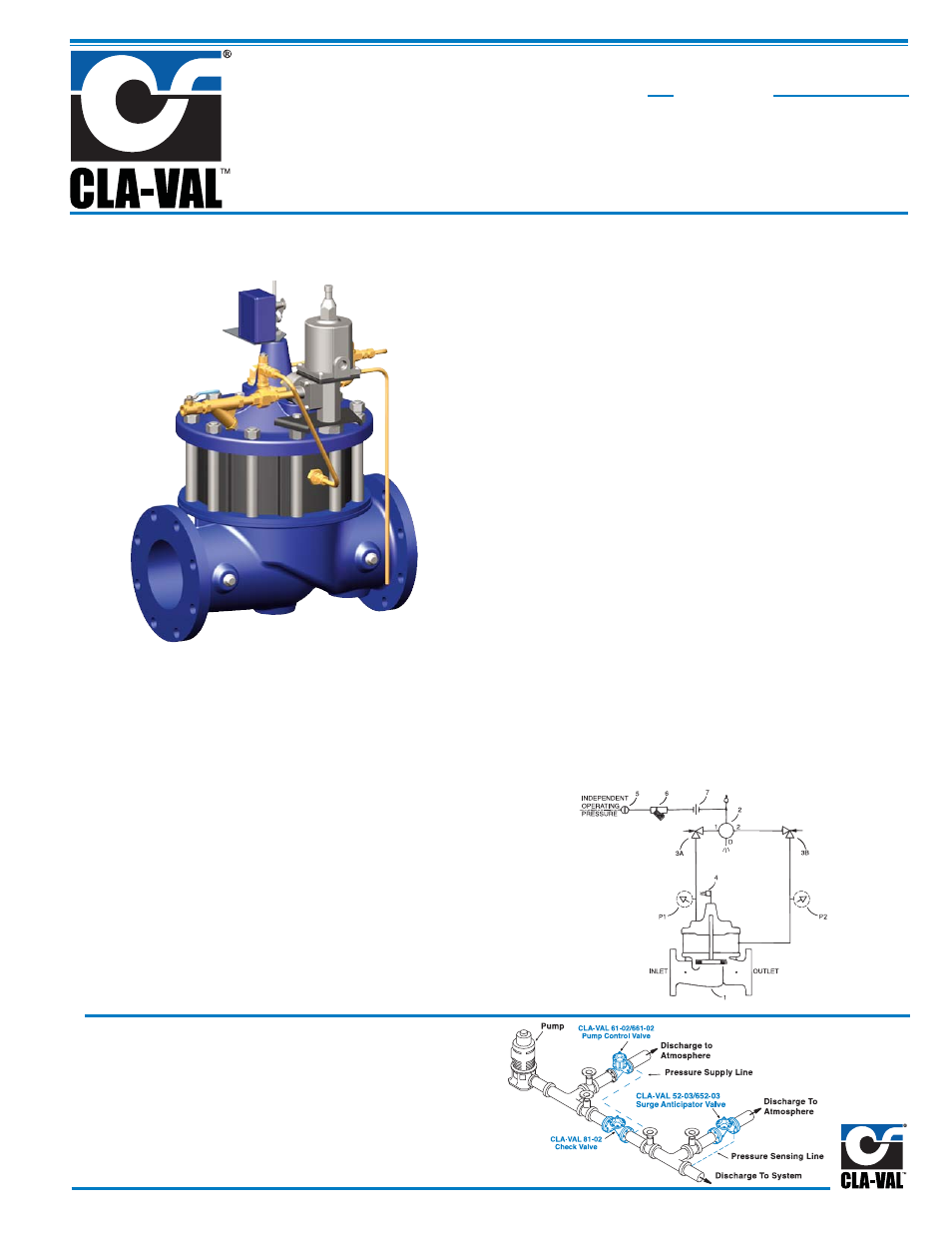
Typical Installation
Install Model 61-02/661-02 valve as shown. Use a minimum of
1/2" tubing to connect operating pressure connection of the
valve to the system side of check valve. Flexible conduit
should be used for electrical connections to the solenoid con-
trol and the limit switch assembly. A Model 52-02/652-03 Surge
Anticipator is recommended for power failure and surge pro-
tection.
Schematic Diagram
Item Description
1
Powertrol (Main Valve)
2
CSM11-A2-2 Solenoid Control
3
CV Flow Control
4
X105LOW Switch Assembly
5
CK (Isolation Valve)
6
X43 "Y" Strainer
7
Union
Item Description
P
X141 Pressure Gauge
•
Prevent Surges in Pipelines
•
Simple Hydraulic Operation
•
Adjustable Opening and Closing Speeds
•
Solenoid Control Can Be Operated Manually
•
Proven Reliable Design
The Cla-Val Model 61-02/661-02 Deep Well Pump Control Valve
is designed to protect pipelines from surges caused by the start-
ing and stopping of deep well pumps. This is a hydraulically op-
erated diaphragm valve which is controlled by a solenoid pilot
valve. Separate adjustable flow control valves in the pilot system
regulate the opening and closing rates. A limit switch on the valve
stem serves as an electrical interlock between the valve and the
pump motor.
The operation of the valve is completely automatic and controlled
by the solenoid valve. With the pump off, the valve is wide open.
When the pump is started, the solenoid is energized and the valve
begins to close slowly, discharging air and the initial rush of sand
and water from the pump column to atmosphere. As the valve
closes the pump output is gradually diverted into the main line,
preventing the development of a starting surge.
When it is time to shut-off the pump, the solenoid is de-energized.
The pump continues to run while the pump control valve opens
slowly, diverting pump output to atmosphere. As pump pressure
gradually decreases, the main line check valve closes slowly, pre-
venting shock or slam during the pump stopping cycle. When the
pump control valve is wide open, the limit switch assembly re-
leases the pump starter and the pump stops.
Note: For main valve option descriptions, refer to 100-02 (61-02) or 100-21
(661-02) Technical Data Sheets.
61-02
MODEL
(Full Internal Port)
661-02
(Reduced Internal Port)