N-x144_iom_18, 1 – starting operation – Cla-Val X144 Technical Manual User Manual
Page 18
SECTION 3: X144 e-FlowMeter Operation
3.1 – Starting Operation
Follow this procedure when starting the installation for the first time or after shutting the system down for
maintenance of the Control Valve.
1) Check all connections to power supply and other User Devices (data loggers, telemetry, etc.)
2) Ensure all wiring is properly connected.
3) Open shut-off valves and allow water into the system.
4) Check the system for water leaks, at both the tapered threads, as well as the straight threads
with knurled lock.
5) Check surrounding piping and auxiliary equipment for leaks.
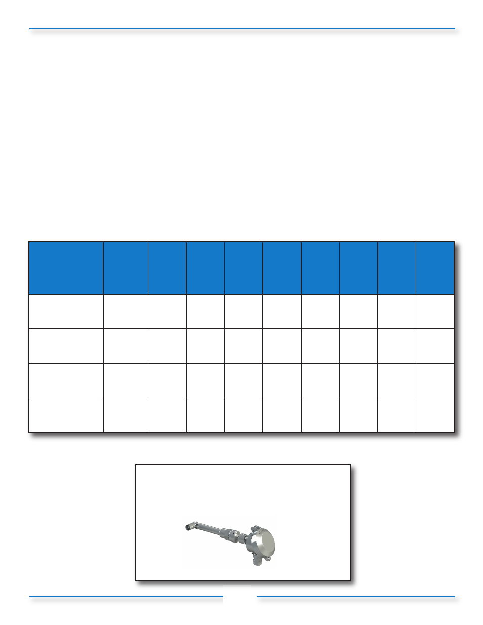
6) Check X144 e-FlowMeter output and verify proper operation at current flow condition
(per table 1):
Table 1: Minimum and Maximum Flow values for X144 e-FlowMeter
15
Log onto www.cla-val.com
and click on the X144 e-FlowMeter
icon to learn more
Line Size
inches (mm)
*2"
(50mm)
(100-49 Body)
2-1/2"
(65mm)
3"
(80mm)
4"
(100mm)
6"
(150mm)
8"
(200mm)
10"
(250mm)
12"
(300mm)
16"
(400mm)
Minimum Flow
(GPM)
10
10
15
25
60
100
160
230
360
Maximum Flow
(GPM)
210
300
460
800
1800
3150
4950
7000
11000
Minimum Flow
(l/S)
0.65
0.65
1.0
1.5
3.8
6.3
10.0
15
23
Maximum Flow
(l/S)
13.3
18.9
29
50
110
200
310
440
700
*2" X144 e-FlowMeter may be installed on new valves only
Note:
Consult Factory for Angle Pattern Applications