Extron Electronics USP 405 User Guide User Manual
Page 61
A-9
USP 405 • Appendix
5.
If the rear panel SDI connector opening is still covered, remove the plastic
cover and position the SDI card at an angle with the SDI connector
protruding from the rear SDI connector opening.
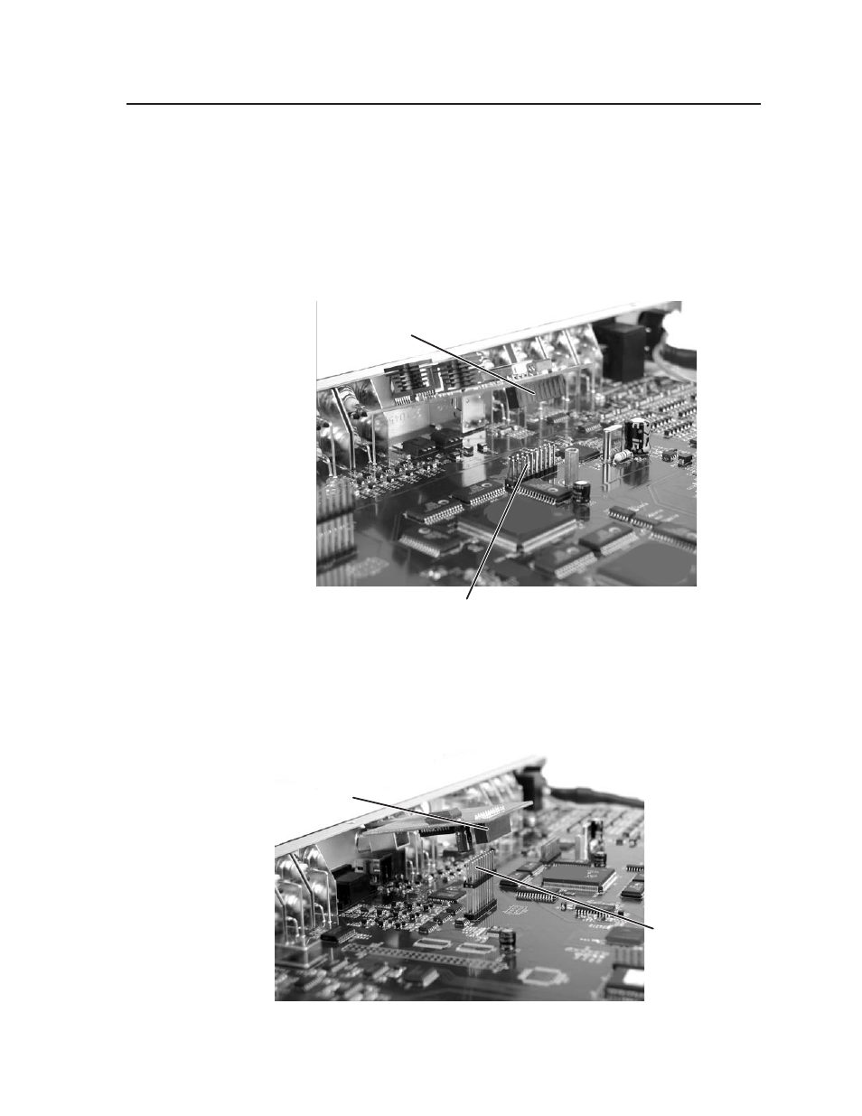
6.
The SDI input card has a 20-pin socket on the underside that should align
with the 20 pins on the main circuit board. Be sure to align the pins
properly, in order to prevent bending the pins, before pressing the SDI card
firmly in place against the standoff. The mounting hole on the SDI card
should now be directly over the standoff. See the picture below.
Input SDI board installation
The SDI output card has a 20-pin socket on the underside which should
align with the 20 pins on the main circuit board. Be sure to align the pins
properly, in order to prevent bending the pins, before pressing the SDI card
firmly in place. See the picture below.
Output SDI board installation
20-pin socket on
back of SDI input card
20-pin connector
on main board
20-pin socket on
back of SDI output card
20-pin connector
on main board
- FOX Matrix 3200 (132 pages)
- ADA 2-4-6 Series (3 pages)
- ADA 6 Component (2 pages)
- AVT 100 (37 pages)
- AVT 200HD Setup Guide (4 pages)
- AVT 200HD User Guide (118 pages)
- AVTrac (482) User Guide (28 pages)
- CAT 5 Receivers (15 pages)
- CAT 5 Transmitters (15 pages)
- CD 400 (3 pages)
- CD 800 (15 pages)
- CD 900 (19 pages)
- CD 100 (18 pages)
- CSVEQ 100 D (2 pages)
- CSVEQ 100 D (38 pages)
- DA RGB_YUV Series (17 pages)
- CVEQ1, CVEQ1 WM, CVEQ1 AAP (17 pages)
- CVEQ_SVEQ 100 Series Setup Guide (2 pages)
- CVDA 6 EQ MX (3 pages)
- CVDA 6 EQ MX (2 pages)
- CVC 300 (8 pages)
- CVC 200 (4 pages)
- CVC 100 (2 pages)
- DDS 402 (54 pages)
- DDS 100 (54 pages)
- DA AV EQ Series (2 pages)
- DVC 501 SD User Guide (38 pages)
- DVC 501 SD Setup Guide (2 pages)
- DTP T USW 333 User Guide (26 pages)
- DTP T USW 333 Setup Guide (4 pages)
- DTP T USW 233 User Guide (26 pages)
- DTP T USW 233 Setup Guide (4 pages)
- DTP HDMI 330 User Guide (19 pages)
- DTP HDMI 330 Setup Guide (2 pages)
- DTP HDMI 301 User Guide (23 pages)
- DTP HDMI 301 Setup Guide (2 pages)
- DTP HDMI 230 User Guide (19 pages)
- DTP HDMI 230 Setup Guide (2 pages)
- DTP HDMI 230 D User Guide (22 pages)
- DTP DVI 330 User Guide (19 pages)
- DTP DVI 330 Setup Guide (2 pages)
- DTP DVI 301 User Guide (23 pages)
- DTP DVI 301 Setup Guide (2 pages)
- DTP DVI 230 User Guide (19 pages)
- DTP DVI 230 Setup Guide (2 pages)