Installation and operation, cont’d, Front panel features, Genlock connections – Extron Electronics USP 405 User Guide User Manual
Page 22: Rs-232 connection
Installation and Operation, cont’d
USP 405 • Installation and Operation
2-6
15
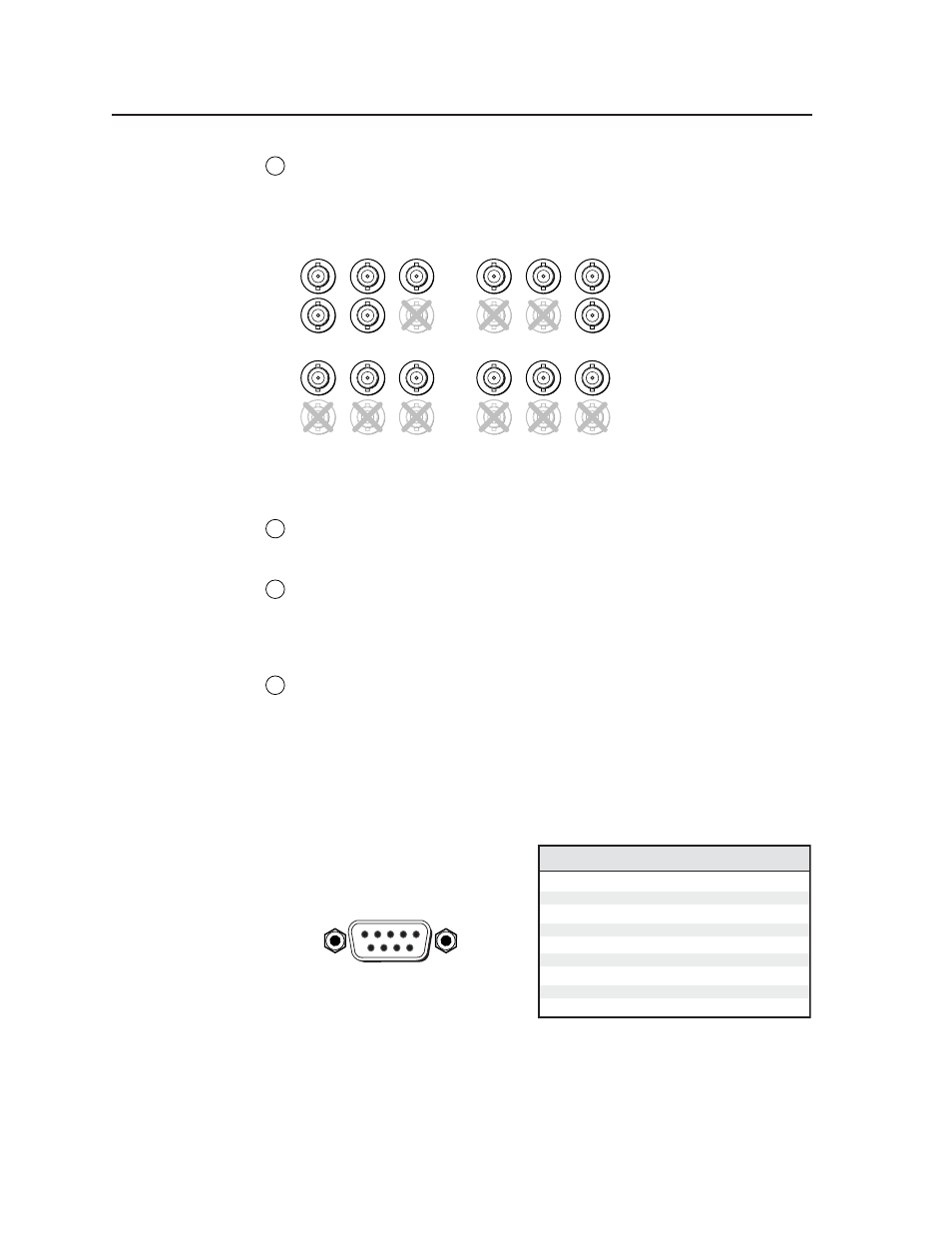
RGB or HDTV component output
— Connect coaxial cables from these
female BNC connectors to an RGB output device or to an HDTV component
video device. Connect cables for the appropriate signal type, as shown
here.
R
/R-Y
G
/Y
B
/B-Y
H
V
S
R
/R-Y
G
/Y
B
/B-Y
H
V
S
R
/R-Y
G
/Y
B
/B-Y
H
V
S
R
/R-Y
G
/Y
B
/B-Y
H
V
S
RGBHV
RGBS
RGsB
HDTV Component Video
Genlock connections
16
Genlock output
— Connect any downstream equipment that requires
genlocking to this female BNC connector to route the black burst signal
throughout the system in broadcast or other sync-critical applications.
17
Genlock input
— Connect an external black burst signal to this female
BNC connector for genlocking the video signal in broadcast or other sync-
critical applications.
RS-232 connection
18
RS-232 port
— This connector provides for two-way RS-232
communication. See the chapter 3, “Serial Communication”, for
information on how to install and use the control software and SIS
commands.
The default protocol is
• 9600 baud
• 1 stop bit
• no parity
• no flow control.
The rear panel RS-232, 9-pin D
connector has the following pin
assignments:
DB9 Pin Locations
Female
5
1
9
6
Front Panel Features
The front panel buttons, controls, and LCD of the USP 405, are shown below.
The front panel buttons can be labeled using the Button-Label Generator
software that is described in chapter 3, “Serial Communication”.
Pin RS-232
function Description
Contact closure
Input 1
1
Transmit data
Tx
2
No connection
–
9
Contact closure
Input 5
8
Contact closure
Input 4
7
Contact closure
Input 3
6
Signal ground
Gnd
5
Contact closure
Input 2
4
Receive data
Rx
3