Cut ceiling tile, Install the speaker on the drop ceiling, Installation — stage three, cont’d – Extron Electronics PoleVault Systems PVS 305SA User Manual
Page 28
PoleVault Systems Installation • Installation — Stage 3
2-17
Installation — Stage Three, cont’d
N
The installation must conform to national and
local electrical codes, and UL requirements.
Refer to the device’s user manual for details.
1. Cut ceiling tile
If installing FF 120 speakers, do the following:
a.
Remove the ceiling tiles where the speakers are to be
installed.
T
For ease of working on the speaker when it is replaced
on the T-frame, remove an adjacent tile(s).
b.
Mark a line 12 inches from one of the short sides of the
tile and cut along the line. Discard the short portion.
T
Use a fine hacksaw blade to cut the tile without
damaging the face and place an empty box under the
tile for support and to collect the waste.
2. Install the speaker on the drop ceiling
a.
At the speaker location, lay one of the supplied T-rails
12 inches from one end of the T-frame. The speaker will
be placed into the small section.
b.
Remove the terminal cover from the rear of a speaker
and attach the anchor ring and cable clamp to the cover.
c.
Place the speaker onto the T-frame and, passing the
speaker cable through the cable clamp, connect the
speaker wires to the speaker terminals:
• Red wire - positive (+)
• Black wire - negative (-)
d.
Reattach the terminal cover.
e.
If possible, bend the seismic tabs over the T-rails.
f.
Replace the ceiling tile.
Repeat the steps 1 and 2 for each speaker that needs to be
installed, connecting the speakers according to the system
preferred (e.g., in parallel, see page 2-18).
If you wish to install an optional seismic/safety cable, at
each speaker location do the following:
g.
Mark, drill and install a lag eye bolt for the seismic/
safety cables (not included) in the structural ceiling
above the speaker location.
h.
Pass the seismic cable through the anchor ring down
to the seismic tab and twist the end around the cable 5
times. Pass the other end up through the lag eye bolt
and twist that end around the cable 5 times.
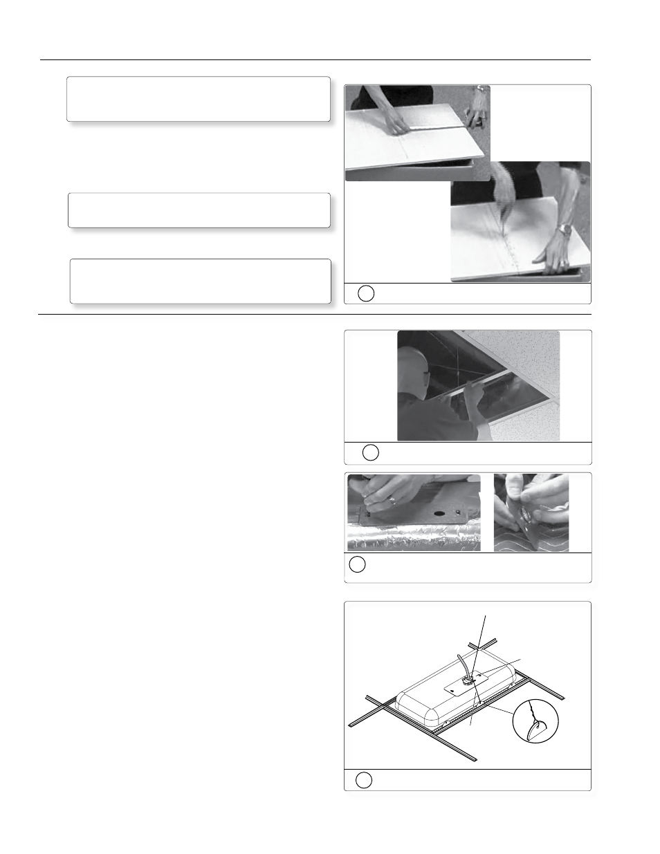
1b
Mark and cut the tile
2h
Attach safety cable
Seismic Safety
Cable
Anchor this end to a
lag eye bolt screwed
into the structural ceiling.
Route the safety cable
through the anchor ring
and the seismic tab.
2a
Place the T-rails on the T-frame
2b
Remove terminal cover and attach clamp
and ring.