Application diagram, Figure 1. connection diagram for an ipl t pc1, Co m tx in s g +5v rx input ir – Extron Electronics IPL T PC1i User Guide User Manual
Page 9: Extron ipl t pc1i, Ipl t pc1 • introduction 3
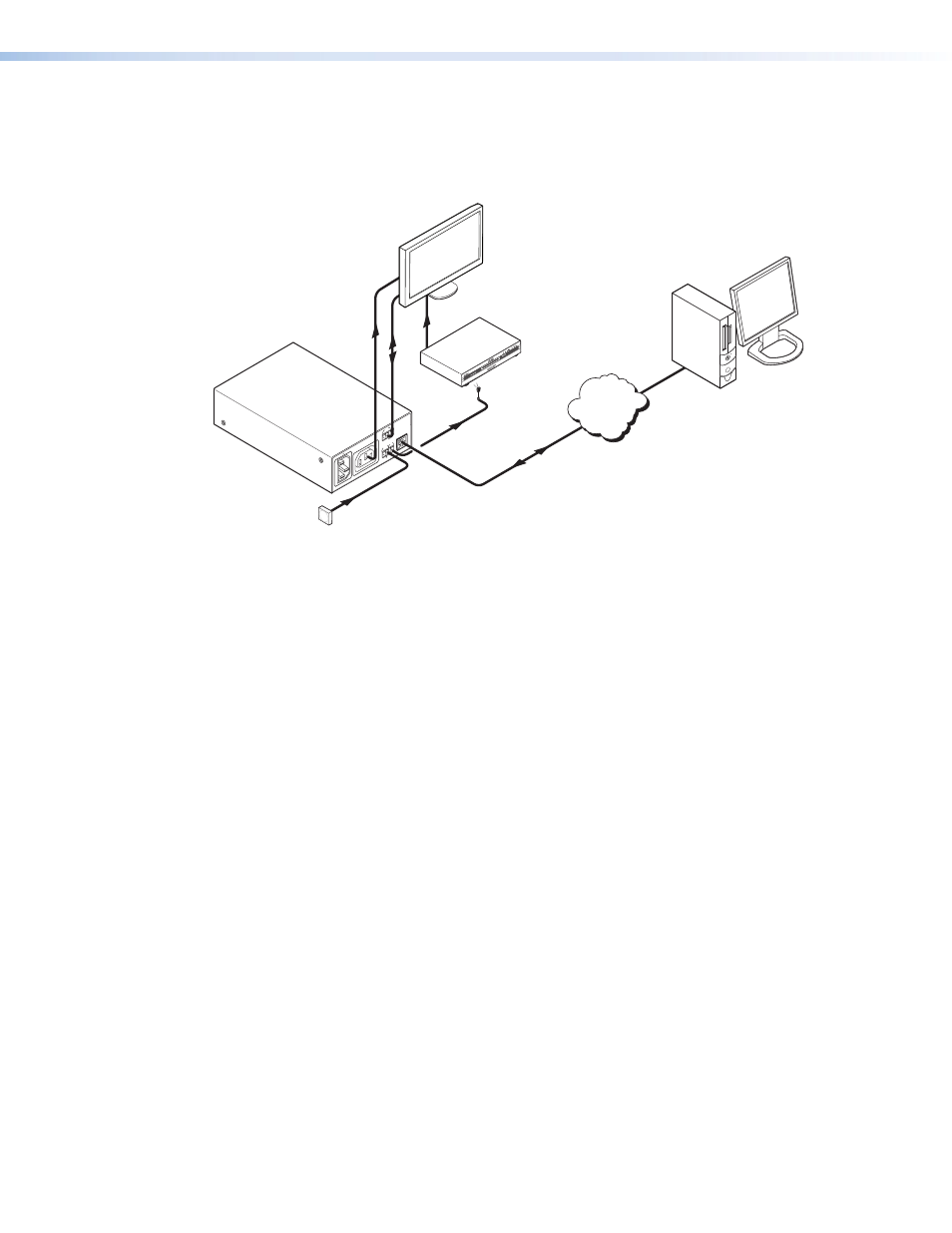
Application Diagram
The following application diagram shows an example of how devices can be connected to
the IPL T PC1 or the IPL T PC1i.
200-240V
50/60H
z
10A MA
X
PO
WER OUTPUT 10A MA
X
LA
N
CO
M
TX
IN
S
G
+5V
RX
INPUT
IR
TCP/IP
Network
ON
Ethernet
DVD
AC Power
RS-232
Plasma
Display
Remote User
Control and
Administrator
Monitoring
Extron
IR Emitter
Kiosk
Button
Extron
IPL T PC1i
Ethernet Control
Interface
Figure 1.
Connection Diagram for an IPL T PC1
IPL T PC1 • Introduction
3
This manual is related to the following products:
See also other documents in the category Extron Electronics Computer Accessories:
- Annotator 300 (4 pages)
- Annotator and USP 507 Output Boards (2 pages)
- Annotator Setup Guide (4 pages)
- Annotator User Guide (108 pages)
- CCR-4BLB AAP (1 page)
- CCR 204 4-User (1 page)
- CIA100 (14 pages)
- CIA101 (14 pages)
- CIA112 (18 pages)
- CIA116 (18 pages)
- CTL101 (34 pages)
- DMP 64 User Guide (146 pages)
- DMP 64 Setup Guide (2 pages)
- DMP 44 LC User Guide (81 pages)
- DMP 44 LC Setup Guide (2 pages)
- DMP 128 User Guide (205 pages)
- DMP 128 Setup Guide (4 pages)
- DAT104 (10 pages)
- DVI-RGB 200 Setup Guide (2 pages)
- DVI-RGB 200 User Guide (19 pages)
- ECP 1000 (18 pages)
- EMOTIA Jr. 800 (2 pages)
- EMOTIA xtreme (2 pages)
- EMOTIA xtreme MX (19 pages)
- Extron TouchLink (78 pages)
- FOX USB Extender Setup Guide (2 pages)
- FOX USB Extender User Guide (19 pages)
- IPL T SFI244 (68 pages)
- IPL T SF Series Setup Guide (51 pages)
- IPL T Series Setup Guide (29 pages)
- IPL T S Series User Guide (79 pages)
- IPL T PCS4 (69 pages)
- IPL T PC1 Setup Guide (27 pages)
- IPL T CR48 (46 pages)
- IPL Pro Series User Guide PRELIMINARY (39 pages)
- IPL Pro Series Setup Guide (8 pages)
- IPI 200 Series Setup Guide (2 pages)
- IPI 100 Series Installation (2 pages)
- IPI 100 Series User Guide (86 pages)
- IPCP Pro Series User Guide (47 pages)
- IPCP Pro Series Setup Guide (10 pages)
- IPCP 505 User Guide (96 pages)
- IPCP 505 Setup Guide (6 pages)
- MGP 464 Series (146 pages)