Wiring the local area network (lan) port, Wiring for ir control, Wiring the local area network [lan – Extron Electronics IPL T PC1i User Guide User Manual
Page 14: Port
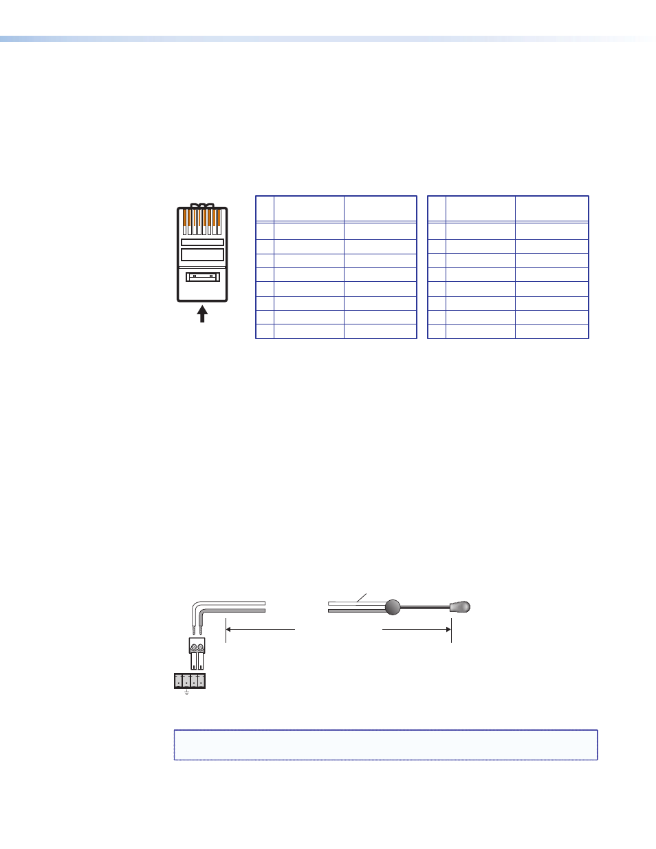
Wiring the Local Area Network (LAN) Port
Wire the connector as shown in the tables below.
•
For 10Base-T (10 Mbps) networks, use a Category 3 or better cable.
•
For 100Base-T (100 Mbps) networks, use a Category 5 cable.
•
Use a straight-through cable to connect to a switch, hub, or router.
•
Use a crossover cable to connect directly to a computer.
A cable that is wired as T568A at one end
and T568B at the other (Tx and Rx pairs
reversed) is a "crossover" cable.
A cable that is wired the same at both ends
is called a "straight-through" cable, because
no pin or pair assignments are swapped.
RJ-45
Connector
Insert Twisted
Pair Wires
12345678
Pins:
Crossover Cable
Straight-through Cable
Pin
1
2
3
4
5
6
7
8
Wire Color
White-orange
Orange
White-green
Blue
White-blue
Green
White-brown
Brown
Wire Color
T568A
T568B
End 1
End 2
End 1
End 2
White-green
Green
White-orange
Blue
White-blue
Orange
White-brown
Brown
Pin
1
2
3
4
5
6
7
8
Wire Color
Blue
White-blue
White-brown
Brown
Wire Color
T568B
T568B
White-orange
White-orange
Orange
Orange
White-green
White-green
Blue
White-blue
Green
Green
White-brown
Brown
Figure 6.
RJ-45 Connector Wiring
Wiring for IR Control
If you intend to control the display device via infrared (IR) commands from the PC1, wire
an Extron IR emitter to a 3.5 mm, 2-pole captive screw connector (provided), and plug the
2-pole connector into the IR Signal and Ground pins (pins 3 and 4) of the shared captive
screw connector on the rear panel.
Alternatively, you can wire the IR emitter to pins 3 and 4 of the provided 4-pole captive
screw plug (and, if desired, also wire a contact closure device to pins 1 and 2 of the same
4-pole connector; see “
” on the next page). Plug the wired
4-pole connector into the rear panel Input/IR connector.
The PC1 provides enough current to power one IR Emitter up to 4000 feet, or up to four
emitters for 100 feet each (see figure 7, below).
IPL T PC1 Shared IR
and Input Connector
IR
Emitter
White Striped Wire Only
Modulated IR
Ground
4000 feet (1574.8 m) Maximum
The PC1 can power a single IR Emitter
up to 4000 feet, or four emitters wired
in parallel up to 100 feet each.
D
E
In
S G
Figure 7.
Wiring for IR Control via an IR Emitter
NOTE: Place the head of the IR emitter over or directly adjacent to the IR receiver of the
controlled device.
IPL T PC1 • Installation and Rear Panels
8