Rear panels – Extron Electronics IPL T PC1i User Guide User Manual
Page 11
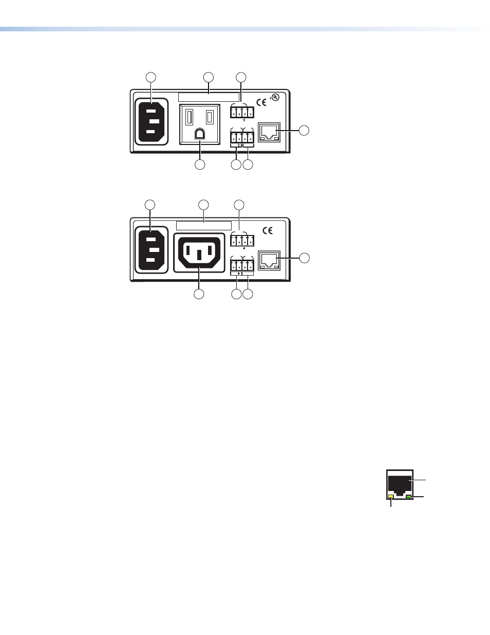
Rear Panels
12A MAX
POWER OUTPUT 12A MAX
LAN
COM
TX
IN
S
G
+5V
RX
INPUT
IR
MAC ADDRESS
100-120VAC 50/60Hz
1
2
3
5
US
LISTED 17TT
AUDIO/VIDEO
APARATUS
®
4
7
6
Figure 2.
IPL T PC1 Rear Panel (120 VAC)
10A MAX
POWER OUTPUT 10A MAX
LAN
COM
TX
IN
S
G
+5V
RX
INPUT
IR
MAC ADDRESS
200-240VAC 50/60Hz
1
2
3
6 5
4
7
Figure 3.
IPL T PC1i Rear Panel (220 VAC)
a
Power connector — Connect a power cord from a wall outlet to this male IEC power
receptacle.
b
UID label — Contains the unique User ID number (MAC address) of the unit (for
example, 00-05-A6-00-00-01).
c
COM port (RS-232) — Connect the output device serial port to this captive screw
connector to enable bidirectional RS-232 device control. This serial port contains the
following four pins, in order from left to right on the rear panel: transmission (Tx),
receiving (Rx), ground (
_
), and +5 V (to tie hand-shaking lines on the controlled device if
needed).
d
LAN connector and LEDs — An Ethernet connection can be used on an ongoing basis
to monitor and control the PC1 and the device connected to it (see “
” for instructions on connecting the host to this port).
•
RJ-45 port — Plug a patch cable into this RJ-45 female socket,
and connect the other end to a network switch, hub, router, or
computer.
•
Link LED — This green LED lights to indicate a good network
connection.
•
Activity LED — This yellow LED blinks to indicate network
activity.
LAN
RJ-45
Port
Link
LED
Activity
LED
IPL T PC1 • Installation and Rear Panels
5