6 maintenance, Advanced instruments inc – Analytical Industries GPR-1600 Series Trace PPB Oxygen Analyzer User Manual
Page 47
Advanced Instruments Inc.
47
6 Maintenance
There are no moving parts in the analyzer given the modular nature of the electronics and sensor. Cleaning the electrical
contacts when replacing the sensor is the extent of the maintenance requirements of this analyzer. Serviceability: Except for
replacing the oxygen sensor, there are no parts inside the analyzer for the operator to service. Only trained personnel with the
authorization of their supervisor should conduct maintenance.
Sensor Replacement:
Periodically, the oxygen sensor will require replacement. The operating life is determined by a
number of factors that are influenced by the user and therefore difficult to predict. The sections
dealing with Specification and Installation Considerations define the normal operating conditions
and expected life of the standard sensor utilized by the GPR-1600 analyzer. As a general
guideline, expected sensor life is inversely proportional to changes in oxygen concentration,
pressure and temperature.
Caution: DO NOT open the oxygen sensor. The sensor contains a corrosive liquid electrolyte
that could be harmful if touched or ingested, refer to the Material Safety Data Sheet contained
in the Owner’s Manual appendix. Avoid contact with any liquid or crystal type powder in or
around the sensor or sensor housing, as either could be a form of electrolyte. Leaking sensors
should be disposed of in accordance with local regulations.
Procedure:
1. Determine your calibration requirements by reviewing the ZERO CALIBRATION and SPAN
CALIBRATION discussions in section 5 Operation. Consult the analyzer specifications for
recovery times and span gas values.
2. Open the door of the analyzer to access the sensor housing.
3. Using the 5/16 wrench supplied loosen but do not remove the clamp bolt located in the
center of the bracket attached to bottom section with the elbow fittings.
4. Rotate the upper section of the sensor housing 90º to disengage from the clamp.
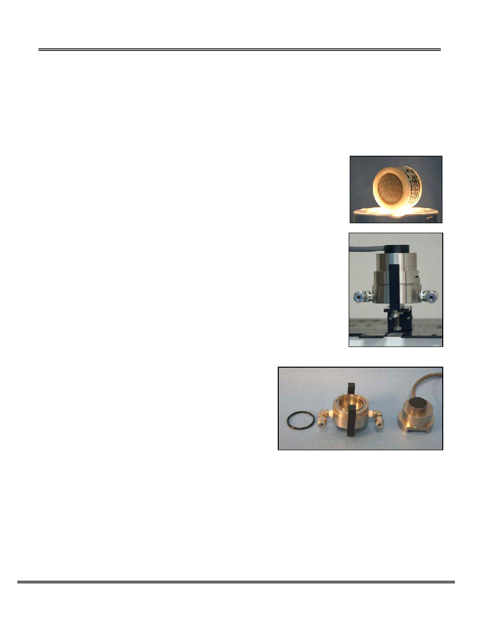
5. Remove the upper section by pulling it straight up and place it on a smooth surface.
6. Remove the old oxygen sensor and dispose of it as you would a battery.
7. Remove the o-ring from the bottom section of the sensor housing.
8. Wipe the o-ring with a damp lint free cloth.
9. Lightly lubricate the o-ring with vacuum grease for optimal seal.
10. Reinstall the o-ring into the bottom section of the sensor housing.
11. From the MAIN MENU select AUTO RANGING as described above.
12. If equipped with SAMPLE/BYPASS valve, place it in the SAMPLE
position.
13. Set the flow rate to 2 SCFH.
14. Connect zero gas or low oxygen content sample gas line to purge the lines and the sensor of oxygen (once reinstalled).
15. Caution: Minimize the time the new sensor is exposed to ambient air.
16. Remove the new oxygen sensor from the shipping bag.
17. Remove the red label and the gold ribbon (shorting device) from the PCB at the rear of the sensor.
18. Place the new sensor in the bottom section of the sensor housing with the PCB facing up.
19. Place the upper section of the sensor housing over the sensor.
20. Gently push the upper section downward and rotate 90º to engage the clamp.
21. Finger tighten the clamp bolt and one full turn with the 5/16 wrench to compressed the o-ring seal.
22. Expect the analyzer reading to recover to ppb levels as described in the analyzer specification.
23. Perform the desired calibration(s).
24. Begin sampling once the analyzer has reached the value of the purge gas.