Advanced instruments inc – Analytical Industries GPR-1600 Series Trace PPB Oxygen Analyzer User Manual
Page 19
Advanced Instruments Inc.
19
Procedure:
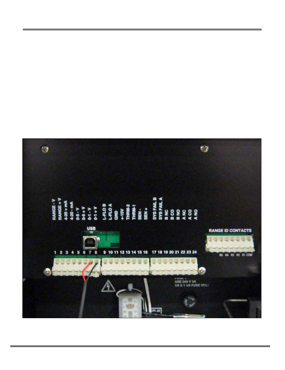
1. As illustrated above the sensor, power and alarm relays and signal output connections are hard wired to screw type
terminal blocks located at the rear of the analyzer.
2. Use a small bladed screwdriver to loosen the appropriate terminal screws as illustrated above.
3. Strip the wires of the cable no more than 3/16 inch.
4. To connect to an active relay or “fail safe”, connect the live cable to the common terminal C and the secondary cable to the
normally open NO terminal.
5. To break the connection upon relay activation, connect the secondary cable to the normally closed NC terminal.
6. Insert the stripped end of the cables into the appropriate terminal slots assuring no bare wire remains exposed that could
come in contact with the back panel of the analyzer enclosure.
7. Tighten the terminal screws to secure the wires of the cable.
Danger: While connecting the cables to the relay terminals, ensure there is no voltage on the cables to prevent electric shock
and possible damage to the analyzer. Caution: Assure the stripped wire ends of the cable are fully inserted into the terminal
slots and do not touch each other or the back panel of the analyzer enclosure.
Interconnections for the optional wall mount enclosure pictured below.