Advanced instruments inc, Span gas preparation – Analytical Industries GPR-1600 Series Trace PPB Oxygen Analyzer User Manual
Page 22
Advanced Instruments Inc.
22
1. The sensor has not been installed at the factory (in standard configuration there are no valves to isolate the sensor) and it
will be necessary to install the sensor in the field.
2. As described above the following steps should already be completed:
a) Secure the sensor housing bracket with two 6/32 mounting screws, in the preferred position the upper section with the
interconnection cable should be facing the ceiling;
b) connect the gas lines;
c) electrical connections.
1. Caution: Do not change the factory settings until instructed to do in this manual.
2. Purge the oxygen trapped in the newly connected gas lines for 3-5 minutes.
3. Flow zero gas or sample gas with a low ppm oxygen concentration to the analyzer at the predetermined flow rate of 1
SCFH.
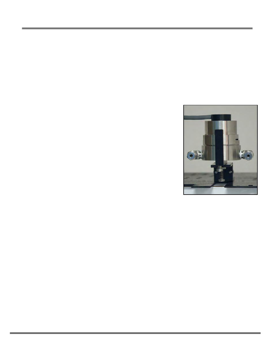
4. Using the 5/16 wrench supplied loosen but do not remove the clamp bolt located under the sensor housing, see photo.
5. Rotate the upper section of the sensor housing 90º to disengage from the clamp.
6. Remove the upper section by pulling it straight up and place it on a smooth
surface.
7. Select the AUTO RANGING option from the SAMPLE menu with gas flowing to the
analyzer.
8. Remove the oxygen sensor from the bag and remove the red shorting device
(including the gold ribbon) from the PCB located at the rear of the sensor.
9. Minimize the time the sensor is exposed to ambient air.
10. Immediately place the sensor in the bottom section of the sensor housing with the
PCB facing up.
11. Immediately place the upper section of the sensor housing over the sensor, gently
push the upper section downward and rotate 90º to engage the clamp.
12. Finger tighten the clamp bolt and then tighten it one full turn with the 5/16 wrench
to securely lock the two sections of the sensor housing.
13. The analyzer will OVER RANGE for a short period of time as indicated by the
graphical LCD display.
14. Wait until the display shows a meaningful oxygen reading and begins to approach
the expected oxygen content of the sample gas.
Span Gas Preparation
The analyzer must be calibrated periodically. See the Calibration section below for recommendations.
Caution: Do not contaminate the span gas cylinder when connecting the regulator. Bleed the air filled regulator (faster and
more reliable than simply flowing the span gas) before attempting the initial calibration of the instrument.
Required components:
¾ Certified span gas cylinder with an oxygen concentration, balance nitrogen, approximating 80% of the full scale range
above the intended measuring range.
¾ Regulator to reduce pressure to 30 psig.
¾ Flow meter to set the flow between 1 SCFH,
¾ Suitable fittings and 1/8” dia. 4-6 ft. in length of metal tubing to connect the regulator to the flow meter inlet
¾ Suitable fitting and 1/8” dia. 4-6 ft. in length of metal tubing to connect from the flow meter vent to tube fitting designated
SAMPLE IN on the GPR-1600.
Procedure:
1. With the span gas cylinder valve closed, install the regulator on the cylinder.
2. Open the regulator’s exit valve and partially open the pressure regulator’s control knob.
3. Open slightly the cylinder valve.
4. Loosen the nut connecting the regulator to the cylinder and bleed the pressure regulator.
5. Retighten the nut connecting the regulator to the cylinder
6. Adjust the regulator exit valve and slowly bleed the pressure regulator.
7. Open the cylinder valve completely.
8. Set the pressure between 5-30 psig using the pressure regulator’s control knob.
9. Caution: Do not exceed the recommended flow rate. Excessive flow rate could cause the backpressure on the sensor
and may result in erroneous readings and permanent damage to the sensor.