2 × 12a digital dual microdlynx, Non-isolated dc-dc power modules, Datasheet – GE Industrial Solutions 2 × 12A Digital Dual Output MicroDLynx User Manual
Page 29
GE
Datasheet
2 × 12A Digital Dual MicroDlynx
TM
: Non-Isolated DC-DC Power Modules
4.5Vdc –14.4Vdc input; 0.51Vdc to 5.5Vdc output; 2 × 12A Output Current
February 14, 2014
©2014 General Electric Corporation. All rights reserved.
Page 29
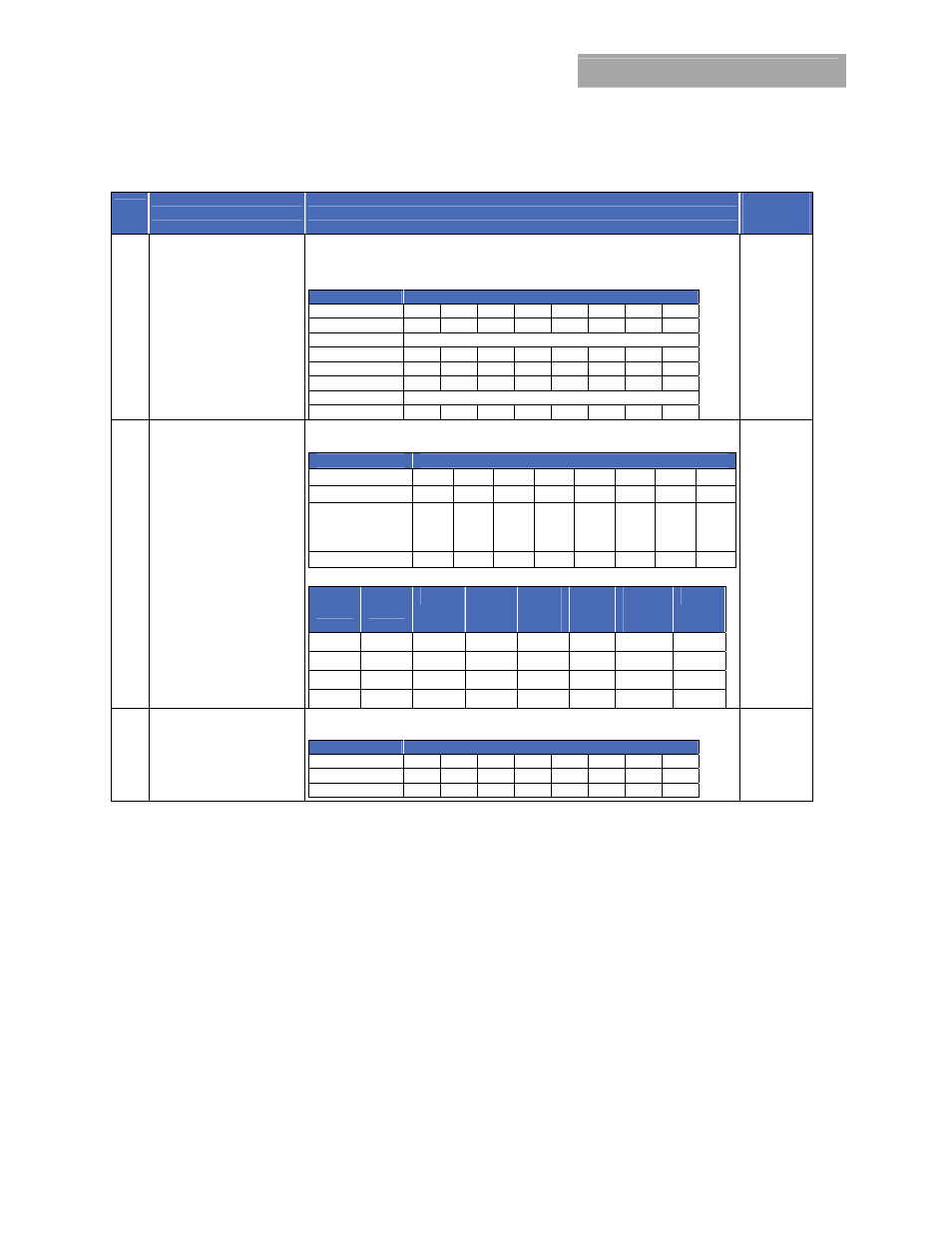
Table 6 (Continued)
Hex
Code
Command
Brief Description
Non-Volatile
Memory
Storage
D6 STEP_VREF_MARGIN_LOW
Applies a fixed negative offset to the reference voltage. Adjustment is -20% to 0% in
2mV steps. Permissible values range between -120mV and 0mV) The offset is
calculated as (STEP_VREF_MARGIN_HIGH + VREF_TRIM)x2
-9
.Exponent fixed at -9(dec).
Net output voltage includes VREF_TRIM adjustment and ranges from -30% to 10%
Format
Linear, two’s complement binary
Bit Position
7 6 5 4 3 2 1 0
Access
r r r
r
r
r
r r
Function
Mantissa
Default Value
V V V V V V V V
Bit Position
7 6 5 4 3 2 1 0
Access
r r r/w
r/w
r/w
r/w
r/w r/w
Function
Mantissa
Default Value
V V V V V V V V
YES
D7 PCT_VOUT_FAULT_PG_LIMIT
Single command to set PGOOD, VOUT_UNDER_VOLTAGE(UV) and
VOUT_OVER_VOLTAGE(OV) limits as percentage of nominal
Format
Unsigned Binary
Bit Position
7 6 5 4 3 2 1 0
Access
r r r
r
r
r
r/w r/w
Function
X X X X X X
PCT_
MSB
PCT_
LSB
Default Value
0 X X X X X X 0
PAGE Command Truth Table
PCT_M
SB
PCT_L
SB
UV (%)
PGL
LOW
(%)
PGL
HIGH
(%)
PGH
HIGH
(%)
PGH
LOW
(%)
OV (%)
0 0
-16.67
-12.5
-8.33
12.5
8.33
16.67
0 1
-12.5
-8.33
-4.17
8.33
4.17
12.5
1 0
-29.17
-20.83
-16.67
8.33
4.17
12.5
1 1
-41.67
-37.5
-33.33
8.33
4.17
12.5
D8 SEQUENCE_TON_TOFF_DELAY
Used to set delay to turn-on or turn-off modules as a ratio of TON_RISE. Values can
range from 1 to 7
Format
Unsigned Binary
Bit Position
7 6 5 4 3 2 1 0
Access
r/w r/w r/w
r
r/w
r/w
r/w r
Default Value
0 0 0 0 0 0 0 0