2 × 12a digital dual microdlynx, Non-isolated dc-dc power modules, Datasheet – GE Industrial Solutions 2 × 12A Digital Dual Output MicroDLynx User Manual
Page 20
GE
Datasheet
2 × 12A Digital Dual MicroDlynx
TM
: Non-Isolated DC-DC Power Modules
4.5Vdc –14.4Vdc input; 0.51Vdc to 5.5Vdc output; 2 × 12AOutput Current
February 14, 2014
©2014 General Electric Corporation. All rights reserved.
Page 20
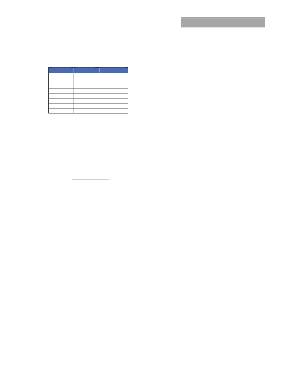
Table 5
Rise Time
Exponent
Mantissa
600μs 11100
00000001010
900μs 11100
00000001110
1.2ms 11100
00000010011
1.8ms 11100
00000011101
2.7ms 11100
00000101011
4.2ms 11100
00001000011
6.0ms 11100
00001100000
9.0ms 11100
00010010000
Output Voltage Adjustment Using the PMBus
The VREF_TRIM parameter is important for a number of
PMBus commands related to output voltage trimming, and
margining. Each of the 2 output voltages of the module shall
be set as the combination of the voltage divider formed by
RTrim and a 20kΩ upper divider resistor inside the module,
and the internal reference voltage of the module. The
reference voltage V
REF
shall be nominally set at 600mV, and
the output regulation voltage is then given by
REF
OUT
V
RTrim
RTrim
V
×
+
=
1
1
20000
1
.
REF
OUT
V
RTrim
RTrim
V
×
+
=
2
2
20000
2
.
Hence the module output voltages shall be dependent on
the value of RTrim1 and Rtrim2 which are connected
external to the module.
The VREF_TRIM parameter is used to apply a fixed offset
voltage to the reference voltage shall be specified using the
“Linear” format and two bytes. The exponent is fixed at –9
(decimal). The resolution of the adjustment is 7 bits, with a
resulting step size of approximately 0.4%. The maximum
trim range is -20% to +10% of the nominal reference
voltage(600mV) in 2mV steps. Permissible values range from
-120mV to +60mV
When PMBus commands are used to trim or margin the
output voltage, the value of V
REF
is what is changed inside
the module, which in turn changes the regulated output
voltage of the module.
The nominal output voltage of the module shall be
adjustable with a minimum step size of 0.4% over a +10% to
-20% range from nominal using the VREF_TRIM command
over the PMBus.
The VREF_TRIM command shall be used to apply a fixed
offset voltage to either of the output voltage command
value using the “Linear” mode with the exponent fixed at –9
(decimal). The value of the offset voltage shall be given by
9
)
(
2
_
−
×
=
TRIM
VREF
V
offset
REF
This offset voltage shall be added to the voltage set through
the divider ratio and nominal V
REF
to produce the trimmed
output voltage. If a value outside of the +10%/-20%
adjustment range is given with this command, the module
shall set it’s output voltage to the upper or lower limit value
(as if VOUT_TRIM, assert SMBALRT#, set the CML bit in
STATUS_BYTE and the invalid data bit in STATUS_CML.
Output Voltage Margining Using the PMBus
Each output of the module shall also have its output voltage
margined via PMBus commands. The command
STEP_VREF_MARGIN_HIGH shall set the margin high voltage,
while the command STEP_VREF_MARGIN_LOW sets the
margin low voltage. Both the STEP_VREF_MARGIN_HIGH
and STEP_VREF_MARGIN_LOW commands shall use the
“Linear” mode with the exponent fixed at –9 (decimal). Two
bytes shall be used for the mantissa with the upper bit [7] of
the high byte shall be fixed at 0. The actual margined output
voltage shall be a combination of the
STEP_VREF_MARGIN_HIGH or STEP_VREF_MARGIN_LOW
and the VREF_TRIM values as shown below.
9
)
(
2
)
_
_
_
_
(
−
×
+
=
TRIM
VREF
HIGH
MARGIN
VREF
STEP
V
MH
REF
9
)
(
2
)
_
_
_
_
(
−
×
+
=
TRIM
VREF
LOW
MARGIN
VREF
STEP
V
ML
REF
The net permissible voltage range change shall be -30% to
+10% for the margin high command and -20% to 0% for the
margin low command
The module shall support the margined high or low voltages
using the OPERATION command. Bits [5:2] shall be used to
enable margining as follows:
00XX
: Margin
Off
0101 : Margin Low (Act on Fault)
0110 : Margin Low (Act on Fault)
1001 : Margin High (Act on Fault)
1010 : Margin High (Act on Fault)
PMBus Adjustable Overcurrent Warning
The module can provide an overcurrent warning via the
PMBus. The threshold for the overcurrent warning can be
set using the parameter IOUT_OC_WARN_LIMIT. This
command uses the “Linear” data format with a two byte
data word where the upper five bits [7:3] of the high byte
represent the exponent and the remaining three bits of the
high byte [2:0] and the eight bits in the low byte represent
the mantissa. The exponent is fixed at –1 (decimal). The
upper five bits of the mantissa are fixed at 0 while the lower
six bits are programmable with a default value of 19A
(decimal). The resolution of this warning limit is 500mA. The
value of the IOUT_OC_WARN_LIMIT can be stored to non-
volatile memory using the STORE_DEFAULT_ALL command.
Temperature Status via PMBus
The module will provide information related to temperature
of the module through the READ_TEMPERATURE_2
command. The command returns external temperature in
degrees Celsius. This command shall use the “Linear” data