2 × 12a digital dual microdlynx, Non-isolated dc-dc power modules, Datasheet – GE Industrial Solutions 2 × 12A Digital Dual Output MicroDLynx User Manual
Page 14: Analog feature descriptions
GE
Datasheet
2 × 12A Digital Dual MicroDlynx
TM
: Non-Isolated DC-DC Power Modules
4.5Vdc –14.4Vdc input; 0.51Vdc to 5.5Vdc output; 2 × 12AOutput Current
February 14, 2014
©2014 General Electric Corporation. All rights reserved.
Page 14
Analog Feature Descriptions
Remote On/Off
The module can be turned ON and OFF either by using the
ON/OFF pin (Analog interface) or through the PMBus
interface (Digital). The module can be configured in a
number of ways through the PMBus interface to react to the
two ON/OFF inputs:
• Module ON/OFF can be controlled only through
the analog interface (digital interface ON/OFF
commands are ignored)
• Module ON/OFF can be controlled only through
the PMBus interface (analog interface is ignored)
• Module ON/OFF can be controlled by either the
analog or digital interface
The default state of the module (as shipped from the factory)
is to be controlled by the analog interface only. If the digital
interface is to be enabled, or the module is to be controlled
only through the digital interface, this change must be made
through the PMBus. These changes can be made and
written to non-volatile memory on the module so that it is
remembered for subsequent use.
Analog On/Off
The2 × 12A Digital Dual MicroDlynx
TM
power modules
feature an On/Off pin for remote On/Off operation. Two
On/Off logic options are available. In the Positive Logic
On/Off option, (device code suffix “4” – see Ordering
Information), the module turns ON during a logic High on the
On/Off pin and turns OFF during a logic Low. With the
Negative Logic On/Off option, (no device code suffix, see
Ordering Information), the module turns OFF during logic
High and ON during logic Low. The On/Off signal should be
always referenced to ground. For either On/Off logic option,
leaving the On/Off pin disconnected will turn the module ON
when input voltage is present.
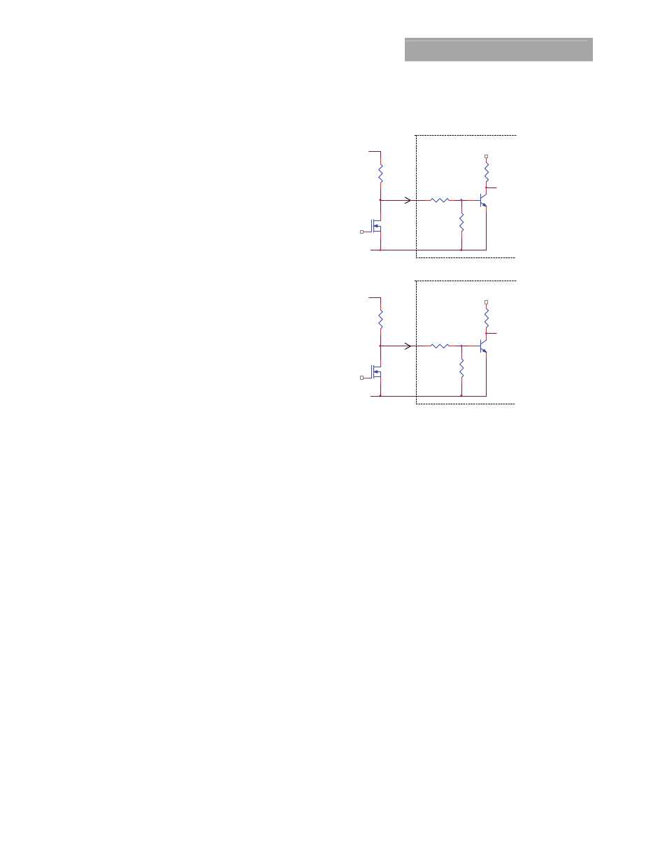
For positive logic modules, the circuit configuration for using
the On/Off pin is shown in Figure 39. For negative logic
On/Off modules, the circuit configuration is shown in Fig. 40.
Digital On/Off
Please see the Digital Feature Descriptions section.
TBD
Figure 39. Circuit configuration for using positive On/Off
logic.
Output 1
Output 2
Figure 40. Circuit configuration for using negative On/Off
logic.
Monotonic Start-up and Shutdown
The module has monotonic start-up and shutdown behavior
for any combination of rated input voltage, output current
and operating temperature range.
Startup into Pre-biased Output
The module can start into a prebiased output on either or
both outputs as long as the prebias voltage is 0.5V less than
the set output voltage.
Analog Output Voltage Programming
The output voltage of each output of the module shall be
programmable to any voltage from 0.6dc to 5.5Vdc by
connecting a resistor between the 2 Trims and SIG_GND
pins of the module. Certain restrictions apply on the output
voltage set point depending on the input voltage. These are
shown in the Output Voltage vs. Input Voltage Set Point Area
plot in Fig. 1. The Upper Limit curve shows that for output
voltages lower than 1V, the input voltage must be lower
than the maximum of 14.4V. If the module can operate at
14.4V below 1V then that is preferable over the existing
upper curve. The Lower Limit curve shows that for output
voltages higher than 0.6V, the input voltage needs to be
larger than the minimum of 4.5V.
DUAL OUTPUT MODULE
22K
22K
+3.3V
+VIN
GND
+
_
V
Q2
ON/OFF1
Rpullup
47K
I
Q1
ON/OFF1
ENABLE1
GND
I
22K
DUAL OUTPUT MODULE
Q2
Q2
+
47K
22K
ON/OFF2
ENABLE2
ON/OFF2
Rpullup
+3.3V
V
_
+VIN