2 × 12a digital dual microdlynx, Non-isolated dc-dc power modules, Datasheet – GE Industrial Solutions 2 × 12A Digital Dual Output MicroDLynx User Manual
Page 23: Summary of supported pmbus commands
GE
Datasheet
2 × 12A Digital Dual MicroDlynx
TM
: Non-Isolated DC-DC Power Modules
4.5Vdc –14.4Vdc input; 0.51Vdc to 5.5Vdc output; 2 × 12A Output Current
February 14, 2014
©2014 General Electric Corporation. All rights reserved.
Page 23
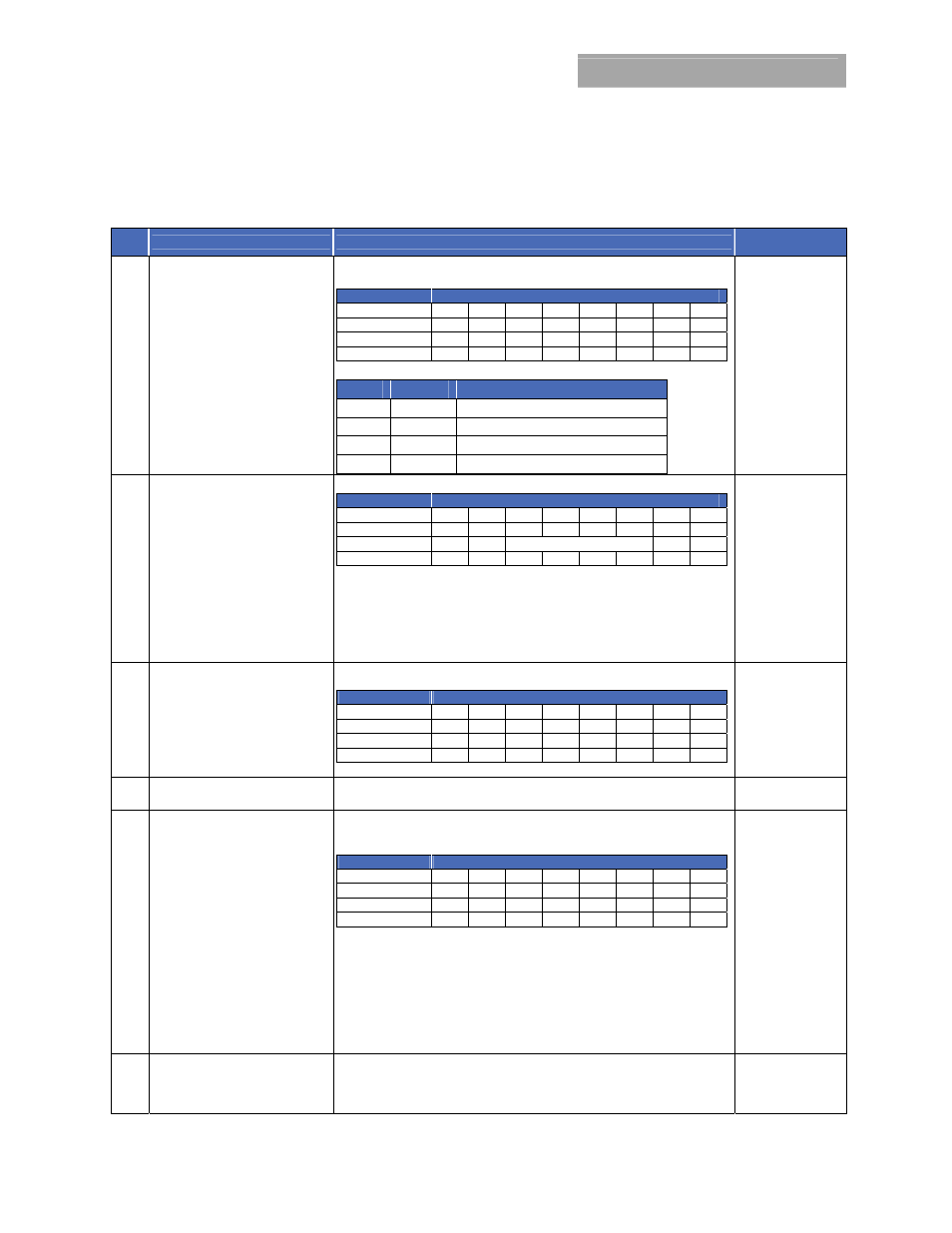
Summary of Supported PMBus Commands
Please refer to the PMBus 1.1 specification for more details of these commands.
Table 6
Hex
Code
Command
Brief Description
Non-Volatile
Memory Storage
00 PAGE
Ability to configure, control and monitor each output by using only one physical
address of the module
Format
Unsigned Binary
Bit Position
7 6 5 4 3 2 1 0
Access
r/w r r
r
r
r
r r/w
Function
PA X X X X X X P0
Default Value
0 X X X X X X 0
PAGE Command Truth Table
PA
P0
Logic Results
0 0
All Commands address first output
0 1
All Commands address second output
1 0
Illegal input, Ignore write
1 1
All Commands address both outputs
01 OPERATION
Turn Module on or off. Also used to margin the output voltage
Format
Unsigned Binary
Bit Position
7 6 5 4 3 2 1 0
Access
r/w r r/w
r/w
r/w
r/w
r r
Function
On X
Margin
X X
Default Value
0 0 0 0 0 0 X X
Bit 7: 0 Output switching disabled
1
Output switching enabled
Margin: 00XX Margin Off
0101 Margin Low ( Act on fault)
0110 Margin Low (Act on fault)
1001 Margin High (Act on fault)
1010 Margin High (Act on fault)
02 ON_OFF_CONFIG
Configures the ON/OFF functionality as a combination of analog ON/OFF pin
and PMBus commands
Format
Unsigned Binary
Bit Position
7 6 5 4 3 2 1 0
Access
r r r
r/w
r/w
r/w
r/w r
Function
X X X pu
cmd
cpr
pol
cpa
Default Value
0 0 0 1 0 1 1 0
Refer to Page 19 for details on pu, cmd, cpr, pol and cpa
YES
03 CLEAR_FAULTS
Clear any fault bits that may have been set, also releases the SMBALERT# signal
if the device has been asserting it.
10 WRITE_PROTECT
Used to control writing to the module via PMBus. Copies the current register
setting in the module whose command code matches the value in the data byte
into non-volatile memory (EEPROM) on the module
Format
Unsigned Binary
Bit Position
7 6 5 4 3 2 1 0
Access
r/w r/w r/w
x
x
x
x x
Function
bit7
bit6
bit5 X X X X X
Default Value
0 0 0 X X X X X
Bit5: 0 – Enables all writes as permitted in bit6 or bit7
1 – Disables all writes except the WRITE_PROTECT, PAGE OPERATION
and ON_OFF_CONFIG (bit 6 and bit7 must be 0)
Bit 6: 0 – Enables all writes as permitted in bit5 or bit7
1 – Disables all writes except for the WRITE_PROTECT, PAGE and
OPERATION commands (bit5 and bit7 must be 0)
Bit7: 0 – Enables all writes as permitted in bit5 or bit6
1 – Disables all writes except for the WRITE_PROTECT command
(bit5 and bit6 must be 0)
YES
15 STORE_USER_ALL
Stores all of the current storable register settings in the EEPROM memory as the
new defaults on power up