Appendix – GE Industrial Solutions ASTAT-IBP Plus User Manual
Page 31
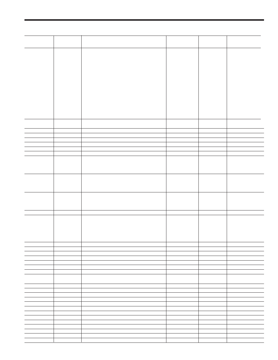
Parameter
Parameter
Function
Read/Write
Range
Comments
number
name
(R/W)
0
Status
Soft starter status
R/-
0 - 14
0: ON
1: STOP
2: LOCK
3: Alarm (errors)
4: PULS
5: RAMP
6: FULL
7: Not Used
8: SOFT
9: Not Used
10: FULL (override)
11: Not used
12: Not Used
13: TACH
14: PUMP
1
M
Motor current
R/-
(%In
or Amps, depending on UF parameter)
2
N
Nominal motor current (%In/Ir)
R/W
40-120
3
L
Current limit (starting) (%Im/In)
R/W
100-450
4
T
Starting torque (% DOL torque)
R/W
10-90
5
a
Acceleration ramp time (sec)
R/W
1-45
6
d
Deceleration ramp time (sec)
R/W
1-60
7
p
Kick start time (msec)
R/W
0-999
10
S
Soft stop control
R/W
0-3
0: OFF
1: ON
2: I3
3 : I4
11
C
Pump control
R/W
0-3
0: OFF
1: ON
2: I3
3: I4
12
P
Kick start control
R/W
0-3
0: OFF
1: ON
2: I3
3: I4
15
LK
Lockout (min.)
R/W
0-45
16
o
Overload trip curve
R/W
0-5
0: OFF
1: N1
2: N2
3: N3
4: C1
5: C2
17
internal use
18
W
Write EEPROM
-/W
1
19
R
Read EEPROM
-/W
1
20
—-
internal use
21
v
Software version
R/-
xxx
vxxx
22
—-
internal use
23
—-
internal use
24
1r
Programmable relay 11-12-14
R/W
22-30
See programmable
relays functions in page 3-6
25
2r
Relay 23-24
R/W
20
26
3r
Programmable relay 33-34
R/W
22-30
27
OC
Overcurrent (%In)
R/W
0-50
0: OFF
28
oc
Overcurrent time (sec)
R/W
0-99
32
UV
Undervoltage (%U)
R/W
0-50
0: OFF
33
uv
Undervoltage time (sec)
R/W
0-99
34
OV
Overvoltage (%U)
R/W
0-30
0: OFF
35
ov
Overvoltage time (sec)
R/W
0-99
36
UC
Undercurrent (%In)
R/W
0-99
0: OFF
37
uc
Undercurrent time (sec)
R/W
0-99
38
PF
Power factor (%)
R/-
00-99
39
U
Nominal voltage (volt)
R/W
200-600
40
V
Line voltage (volt) Phase L1
R/-
6. Appendix
6-2-3. List of parameters that can be controlled by the serial interface
6-4