Programming, 1. keypad and display description, Display – GE Industrial Solutions ASTAT-IBP Plus User Manual
Page 14: Keypad
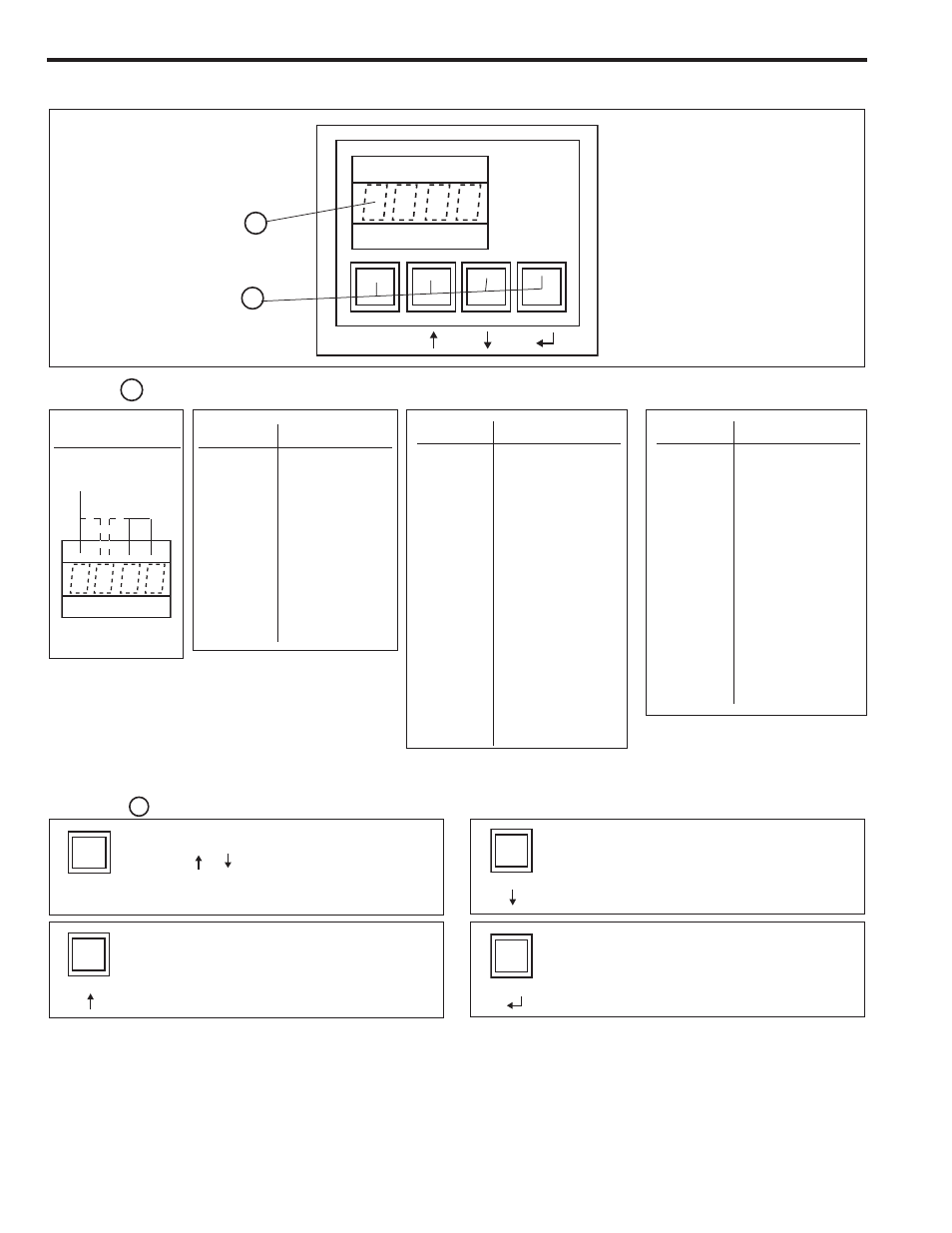
4-1. Keypad and display description
1
2
Display
1
F
V
V
V
F V V V
Error code
E 0 1
0
Frequency out of range
E 0 1
1
Overload trip
E 0 1
3
Loss of synchronism
E 0 1
4
Phase U scr
E 0 1
5
Phase V scr
E 0 1
6
Phase W scr
E 0 1
7
Heatsink overtemperature
E 0 1
8
Motor thermistor
E 0 1
9
Phase U lost
E 0 2
0
Phase V lost
E 0 2
1
Phase W lost
E 0 2
2
Stalled rotor
E 0 2
3
Internal error
E 0 2
5
Long start time
E 0 2
7
Lock-out
E 0 2
8
Undervoltage
E 0 2
9
Overvoltage
E 0 3
0
Undercurrent
E 0 3
1
Overcurrent
F V V V
Status code
O N
Equipment is
connected
to main supply
(equipment is ON)
S T O P
Stop
L O C K
Remote stop
P U L
S
Kick start
R A M P
Acceleration ramp
F U L
L
Full conduction
S O F
T
Soft stop
P U M P
Pump control
T A C H
Linear ramp (tacho)
Keypad
2
SELECTION
Use with
or
to select the parameter or function code
to be displayed and/or modified
SEARCH / ADJUSTMENT
Increases the value of the selected parameter
ENTER / SAVE
- Introduces the new parameter value into memory
- Updates the selected parameter value with the
displayed value
SEARCH / ADJUSTMENT
Decreases the value of the selected parameter
C / V
Data
Function code
C / V
4-1
4. Programming
Displays monitoring, status indications, error messages and function set values
Allows setting of parameters and functions
F F/V V V
Function code (*)
M x x
x
Motor current
v
x x
x
Software version
.
.
.
.
P F x
x
Power factor
.
.
.
.
L x x
x
Current limit
T x x
x
Starting torque
a x x
x
Ramp up time
d x x
x
Ramp down time
S x x
x
Soft stop selection
.
.
.
.
L K x
x
Lock out
.
.
.
.
(*)These are examples. Full details in
sections 4-2, 4-3, 4-4, 4-5 and 4-6
Display Structure