Installation, 1. equipment installation, 2. general – GE Industrial Solutions ASTAT-IBP Plus User Manual
Page 24
Catalog Numbers
Wire Range
Torque, in-lb
CI2K, QI2L, QI2Y, QI2M, QI2Z, QI2N
#14-#2 AWG
125
QI2P, QI2Q
#6 AWG-350 kcmil
275
QI2R, QI2S
#2 AWG-2x250 kcmil (or 1x600 kcmil)
550
5-1. Equipment installation
CAUTION! DISCONNECT POWER BEFORE INSTALLING OR SERVICING
ONLY SPECIALIZED PERSONNEL SHOULD INSTALL THE EQUIPMENT AND ONLY
AFTER HAVING READ THIS USER'S GUIDE.
THE USER IS RESPONSIBLE FOR ANY PHYSICAL INJURY OR MATERIAL DAMAGE
RESULTING FROM MISHANDLING THE EQUIPMENT.
5-2. General
Terminal Connections
Use minimum of 75
°
C copper wire only for connections to ASTAT-IBP Plus terminals. The minimum wire size must conform to the 75
°
C
table according to applicable electrical codes. Tighten connections to the torque values given below. Supply conductors should have,
as a minimum, the same cross section as a full voltage starter.
A
A C
D
D C
SIGNAL
POWER
5. Installation
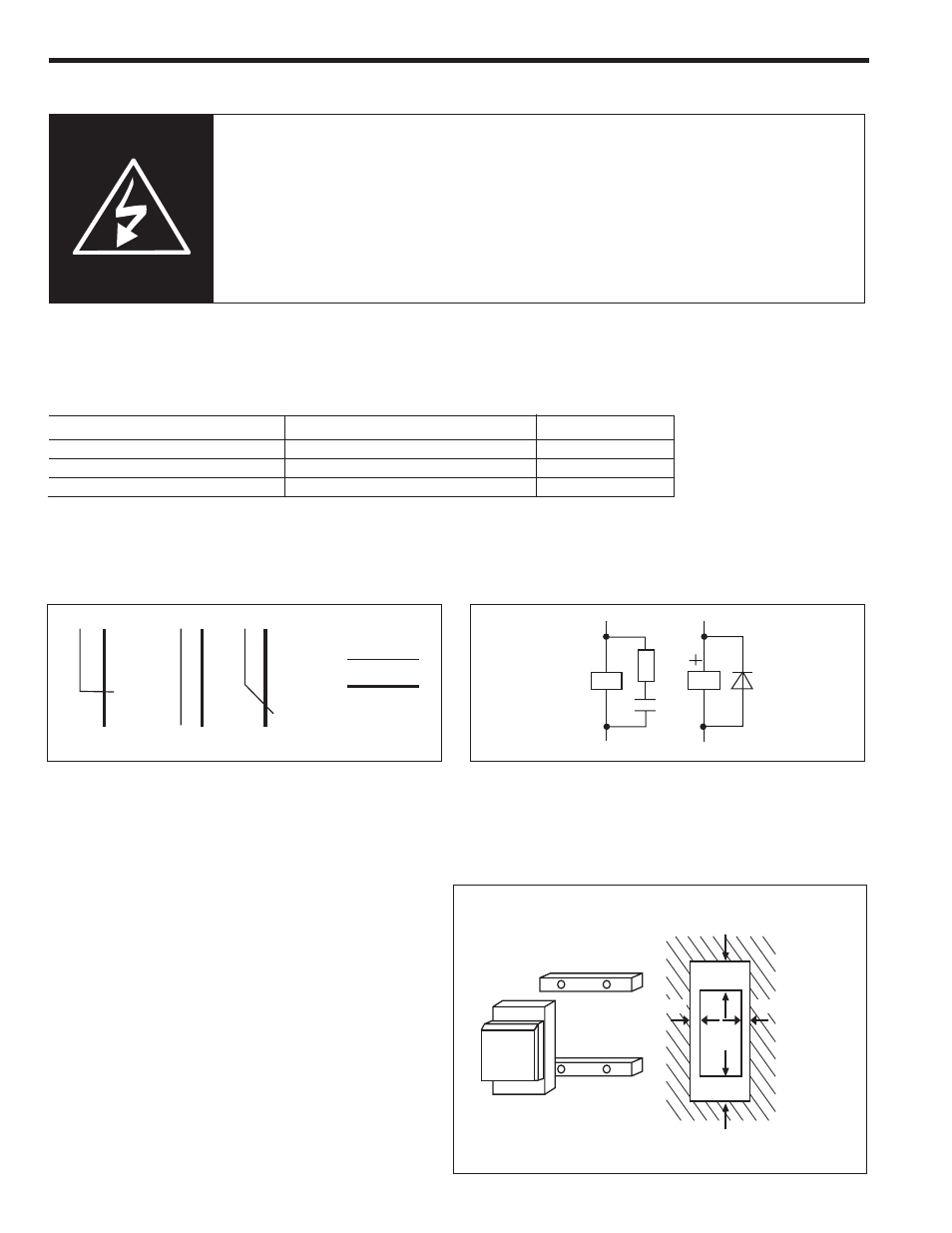
Environment
When installing equipment, keep the following points in mind:
- The equipment should be installed vertically and hang over a
platform or bars. The vertical position is essential for proper cool air
circulation.
- Environmental conditions are in accordance with the following
ranges and maximum values:
- Operating temperature: 0ºC to +55ºC
- Relative humidity (without condensation): 95%
- Maximum altitude: 3000m
Reduce rating by 1.5% / ºC from 40ºC and 1% / 100m from 1000m
- Do not install equipment in environments containing explosive or
flammable gases, or near important heat sources.
- Equipment should be well ventilated, with minimum keeping
clearances as indicated in the illustration.
- When equipment is to be mounted on a platform subject to strong
vibrations, there should be an elastic base to protect the equipment.
- When mounted in an enclosure, the temperature inside the enclosure
must be kept within the range of 0-45
°
C (32-113
°
F).
ASTAT
100mm
150mm
50mm
50mm
5-1
CORRECT
INCORRECT
10 cm
8 cm
Signal Wiring
Signal wiring should be no longer than 18 feet (up to 80 feet when
using shield cable). It must be separated from power wires (line,
motor, commands relays, etc.) by at least four inches and, if they
cross, they should do so at a 90
°
angle.
Coil Surge Suppression
Relays and contactors located in the same housing as the equipment
should have an RC suppressor parallel to the coil (or a reverse
diode, if controlled by DC).
Power Factor Capacitors
Do not install capacitors to correct the power factor between equipment output and motor.
Transformers
If the equipment is fed by a line transformer, its rated power should be at least 1.5 times, but less than 10 times, higher than equipment supply.