GE Industrial Solutions AF-650 GP MultiPulse Drive Panel User Manual
Page 33
MULTIPULSE DRIVE PANEL
33 GE Energy ©2012 GE Company All Rights Reserved
Note: For unmentioned torques, Refer UL508A tables 54.1, 54.2 and 54.3
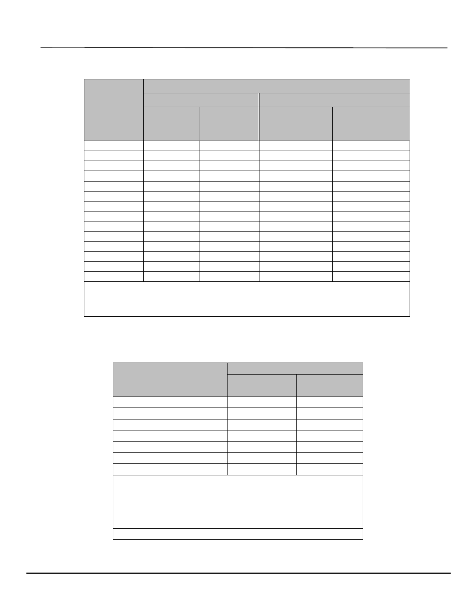
Table 54.1 , Tightening torque for screws
Test wire size
installed in
connector
(AWG)
Tightening torque (lb in.)
Slotted head no 10 and large Hexagonal head - external drive socket
wrench
Slot width -
0.047 inch or
less and slot
length 1/4
inch or less
Slot width -
0.047 inch or
slot length -
over 1/4 inch
Split bolt
connectors
other connectors
18-10
20
35
80
75
8
25
40
80
7
6-4
35
45
165
110
3
35
50
275
150
2
40
50
275
150
1
-
50
275
150
1/0 - 2/0
-
50
385
180
3/0-4/0
-
50
500
250
250-350
-
50
650
325
400
-
50
825
375
500
-
50
825
375
600-750
-
50
1000
375
800-1000
-
50
1100
500
1250-2000
-
-
1100
600
Note : For values of slot width or length not corresponding to those specified, the largest
torque value associated with the conductor size shall be marked. Slot width is the normal
design value. Slot length shall be measured at the bottom of the slot
Table 54.2 , Tightening torque for slotted head screws smaller
than No. 10 intended for use with 8 AWG or smaller conductors
Slot length of screws
a
Tightening torque, lb.in
Slot width of
screw
b
smaller
than 0.047 in
Slot width of
screw
b
0.047 in
and larger
<5/32
7
9
5/32
7
12
3/16
7
12
7/32
7
12
1/4
9
12
9/32
-
15
Above 9/32
-
20
a
For slot length of intermediate values, torques pertaining to next
shorter length shall be utilized. For screws with multiple tightening
means, the largest torques value associated with the conductor size
shall be marked. Slot length shall be measured at the bottom of the
slot
b
Slot width is the nominal design value