GE Industrial Solutions AF-650 GP MultiPulse Drive Panel User Manual
Page 20
MULTIPULSE DRIVE PANEL
20 GE Energy ©2012 GE Company All Rights Reserved
7) Take a picture of the DC bus so
you can see how to put it back
together when done. See figure
6.4 and 6.5.
8) Notice how the insulation paper is
arranged so you can re-assemble
when done. See figure 6.4.
9) Completely remove the DC BUS
from the diodes.
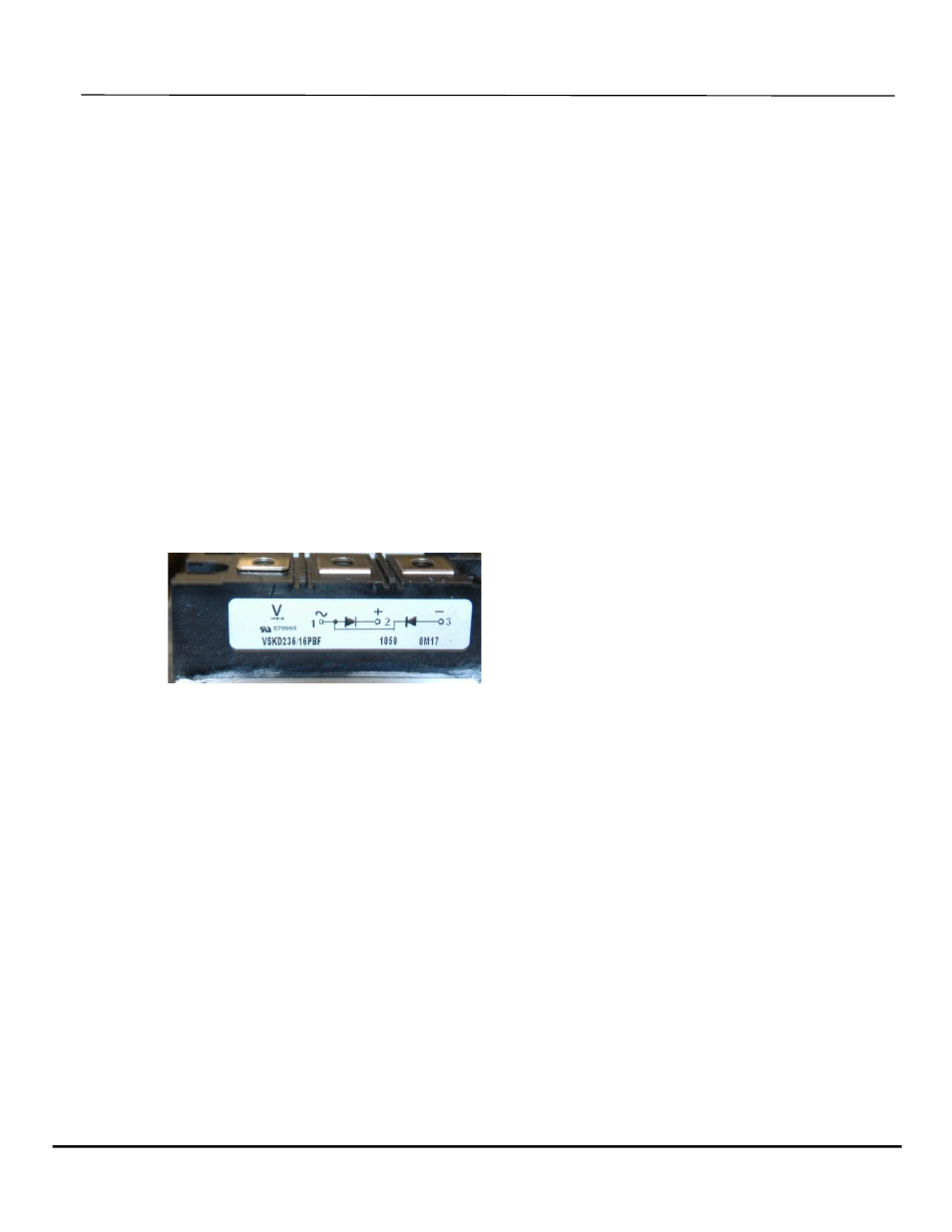
Notice that there are six external
rectifier modules consisting of
(D2+ & D2-)
(D5+ & D5-)
(D8+ & D8-)
(D3+ & D3-)
(D6+ & D6-)
(D9+ & D9-)
Each module has three terminals:
(AC) (–) (+)
10) Once the DC bus is removed and
while C1 and C2 are still open each
diode can be tested individually
Check each diode with diode
meter and record on the chart
found on the next page.
Keep in mind you should see
continuity with your BLK lead on
the + output of each rectifier to AC
input.
And NO CONTINUITY with the RED
lead on the (+) output of each
rectifier to the AC input.
Then one should see continuity
with RED lead on the (– ) output of
each rectifier to the AC input.
And NO CONTINUITY with the BLK
lead on the ( – ) output of each
rectifier to the AC input.
11) Replace each defective rectifier
module being sure to spread a thin
layer of heat sink compound on
the back before screwing in place),
do not connect (1, 4, 7) to VFD until
step
17.
12) Re-assemble the DC bus onto the
rectifiers
13) Use Dupont make NOMEX 410
new electrical insulation paper as
needed. Try to Keep at least ½”
distance for any path of arc.
14) Leave the DC bus leads OFF from
the VFD (Tape them so they don’ t
short out).
15) While measuring VDC on the DC
Bus, Use a cord to supply 120VAC
through a series light bulb into (2,5)
then (5, 8) then (3, 6) then (6, 9). one
should see about 108VDC each
time.
16) While measuring VDC on the VFD
(+DC,-DC), Feed 120VAC through
the light bulb into VFD (L1, L2) then
(L2, L3), one should see the VFD
capacitors charge to 170VDC each
time.
17) If diodes pass test of step 15 & 16,
reconnect DC bus to VFD and
reconnect (1, 4, 7)
18) Put CR4 back in. Close doors to
protect you from arc flash. Turn on
480V
19) If VFD comes on successfully, turn
480V back off, and connect
harmonic meter
20) Turn 480VAC back on and run at
full speed
21) If each phase current is below 8%
TDH current, your job is a great
success.
22) Turn off the supply breaker, wait
for DC bus to get below 50V
23) Re-assemble hood over the
rectifier section
24) Complete!
Figure 6.6 - External Rectifier sample