Astat-cd plus service instructions – GE Industrial Solutions ASTAT-CD Plus Solid-State Starters User Manual
Page 3
ASTAT-CD Plus Service Instructions
3
Step 8. Remove the 4 screws holding the Power
Supply Board to the black plastic housing
(Figure 6).
Screws to remove
Figure 6. Removing screws holding Power
Supply Board
Step 9.
Lower the top of the Power Supply Board to
view the yellow and blue gate leads to the
SCRs (Figure 7).
NOTE: Check the blue and yellow gate wires
for a number marking before removing
these wires. Each gate wire must have a
number marking correlating to the terminal
numbers on the Power Supply Board (1
through 12) to facilitate reassembly.
Gate leads
Protection Board
Bottom of Power Supply Board
Gate terminal board
Figure 7. Gate leads, Protection and
Power Supply Boards
Step 10. Remove the blue and yellow gate wires from
the small 4- point gate Terminal Boards, 1 on
the component side and 2 on the solder side
of the Power Supply Board, with a small
screwdriver.
These wires must be reconnected to the new
Power Supply Board at the proper numbered
terminals for proper operation of the starter.
Remove the Power Supply Board. Remove
the hex standoffs, nuts and washers from the
Power Supply Board for use on the
replacement board.
Step 11. Reassemble the standoffs to the new Power
Supply Board. Reconnect the gate wires.
Reference Figure 8 for gate lead connections.
Step 12. Reassemble the Logic Board, cover and
terminal connectors using Steps 5 - 6.
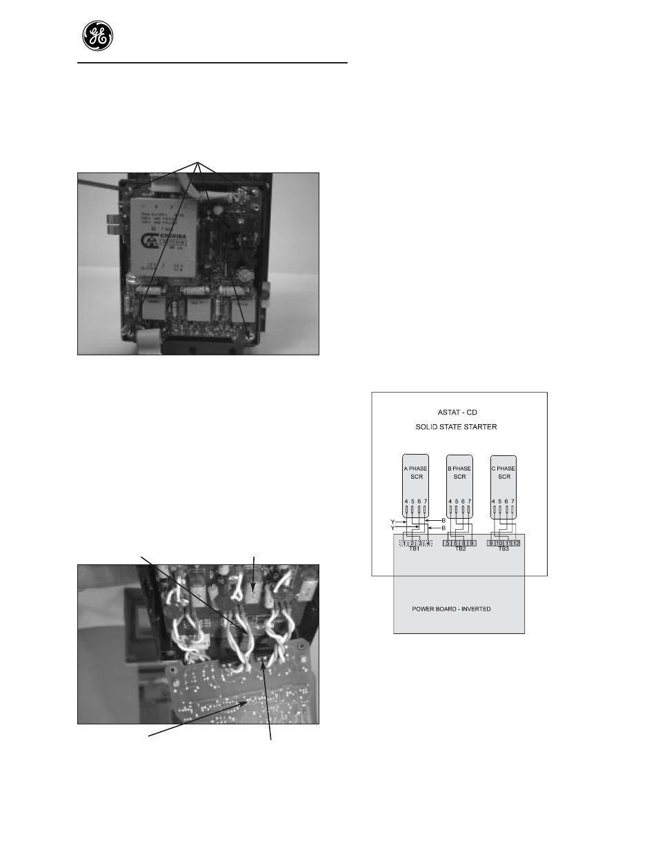
Figure 8. Gate lead connections
Y = yellow wire.
B = blue wire.
SCR lead pairs are to be twisted to reduce EMI
(not shown in sketch).