Astat-cd plus service instructions – GE Industrial Solutions ASTAT-CD Plus Solid-State Starters User Manual
Page 2
ASTAT-CD Plus Service Instructions
2
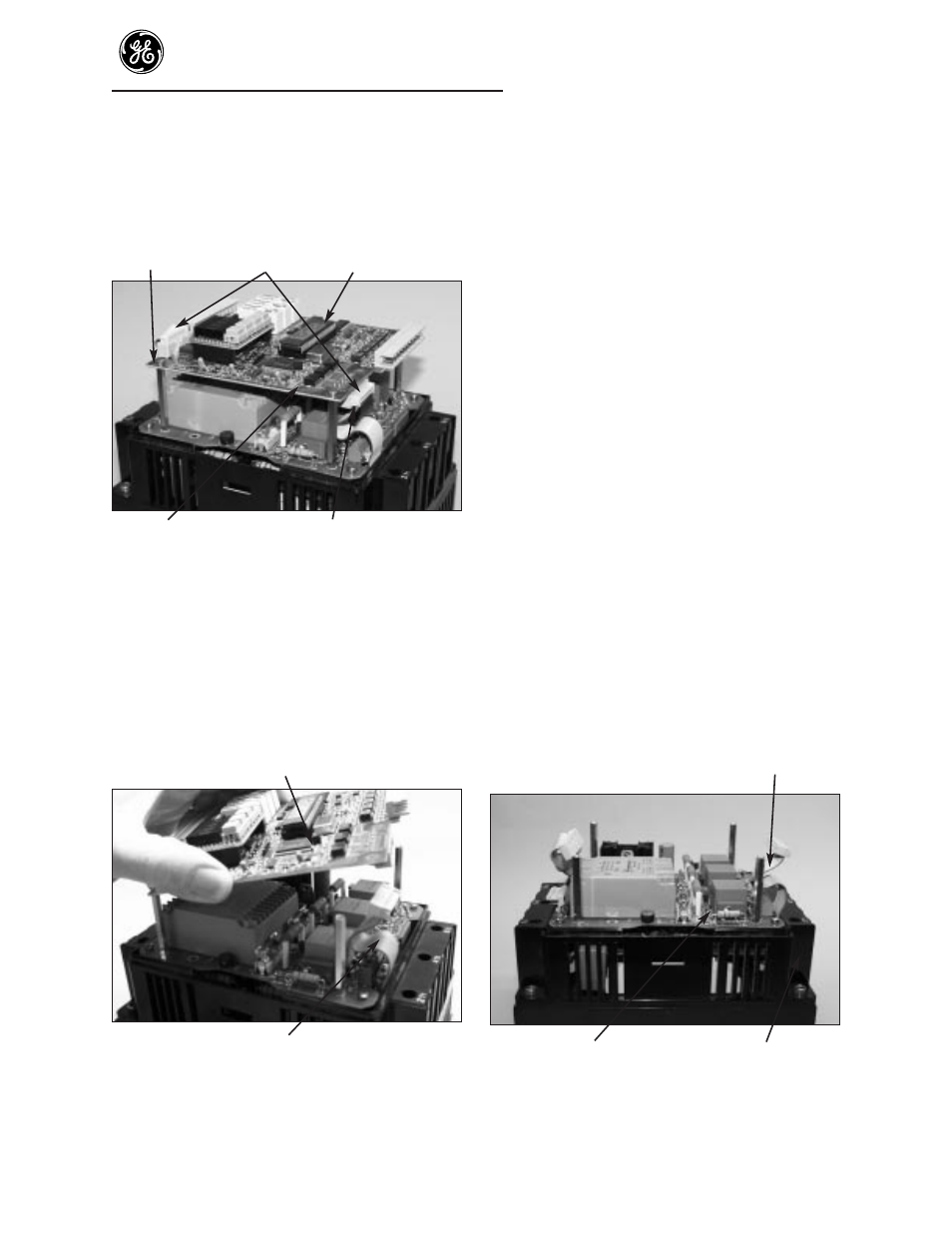
To replace Logic Board (top board)
Important: Always handle boards by
edges and do not distort parts on board.
Unplug Logic
Screws
ribbon cable
Board
Power
Unplug ribbon cable
Supply Board
(Step3)
Figure 3. Board and part locations
Step 3. To remove Logic Board, unplug the two
ribbon cables from the Logic Board.
Step 4. Remove the 4 corner screws holding the
Logic Board to the stand-offs below the Logic
Board. Remove the Logic Board.
Logic Board
Ribbon cable
Figure 4. Logic Board removal
Step 5. Reassemble Logic Board to the starter. With
the display on the Logic Board at the upper
left corner, place the board on the standoffs
and attach the Logic Board in the reverse
order as listed in Steps 3 and 4 above. Make
sure the ribbon cable at the bottom of the
ASTAT is fully seated on both circuit boards
and that the ribbon cable will not interfere
with or touch the cover.
Step 6. Reassemble the plastic cover and the terminal
connectors by lowering the cover over the
boards. Carefully push down the cover until
the two tabs snap into place. It may be
necessary to push in slightly on the outside of
the lower plastic housing.
Replace the terminal connectors through the
plastic cover, onto the connector strips. Make
certain that the terminal connectors snap into
place.
To replace Power Supply Board
NOTE: POWER MUST BE REMOVED
BEFORE SERVICING.
The Power Supply Board location is shown
in Figure 5. It has gray and orange
transformers visible from the sides.
Step 7. Remove the cover and Logic Board using
steps 1 - 4.
Ribbon cable
Power Supply Board
Control housing
Figure 5. Power Supply Board