Astat-cd plus service instructions – GE Industrial Solutions ASTAT-CD Plus Solid-State Starters User Manual
Page 14
ASTAT-CD Plus Service Instructions
14
Step 8. Reassemble the plastic cover and the terminal
connectors by lowering the cover over the
boards. Carefully push down the cover until
the two tabs snap into place. It may be
necessary to push in slightly on the outside of
the lower plastic housing.
Step 9. Replace the terminal connectors through the
plastic cover, onto the connector strips. Make
certain that the terminal connectors snap into
place (Figure 2).
Step 10. Replace the front steel cover using the 4
Phillips screws (Figure 1).
To replace Power Supply Board
NOTE: POWER MUST BE REMOVED
BEFORE SERVICING.
Step 11. Remove the cover and Logic Board using
steps 1 - 6.
The Power Supply Board location is shown in
Figure 4. It has gray and orange transformers
visible from the sides.
Ground wire
Hex standoff
Ribbon cable
Power Supply Board
Control housing
Figure 4. Removing Logic Board
Screws
to remove
Figure 5. Removing screws holding Power
Supply Board.
Step 12. Remove the 4 screws holding the Power
Supply Board to the black plastic housing.
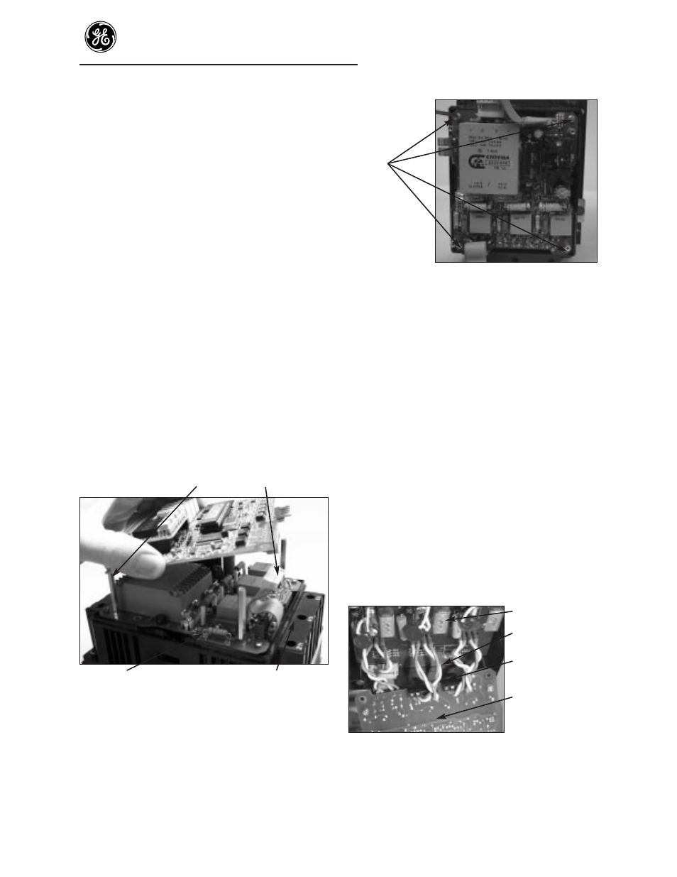
Step 13. If a yellow/green ground wire is connected to
the bottom of the Power Supply Board, it
must be disconnected. Lower the top of the
Power Supply Board to view the yellow and
blue gate leads to the SCRs (Figure 6).
NOTE: Check the blue and yellow gate wires
for a number marking before removing these
wires. Each gate wire must have a number
marking correlating to the terminal numbers
on the Power Supply Board (1 through 12) to
facilitate reassembly.
Step 14. Remove the blue and yellow gate wires from
the small 4- point gate Terminal Boards, 1 on
the component side and 2 on the solder side
of the Power Supply Board, with a small
screwdriver (Figure 6).
Protection Board
Gate leads
Gate Terminal
Board
Bottom of Power
Supply Board
Figure 6. Gate leads, Protection and Power
Supply Boards