Astat-cd plus service instructions, Scr disassembly instructions - sizes l and m – GE Industrial Solutions ASTAT-CD Plus Solid-State Starters User Manual
Page 10
ASTAT-CD Plus Service Instructions
10
To replace the Protection Board.
NOTE: POWER MUST BE REMOVED
BEFORE SERVICING.
Step 14. Remove the cover and Logic Board/ Power
Supply Board assembly using steps 1 - 3, 9-10.
Step 15. Remove 6 wire connectors from the
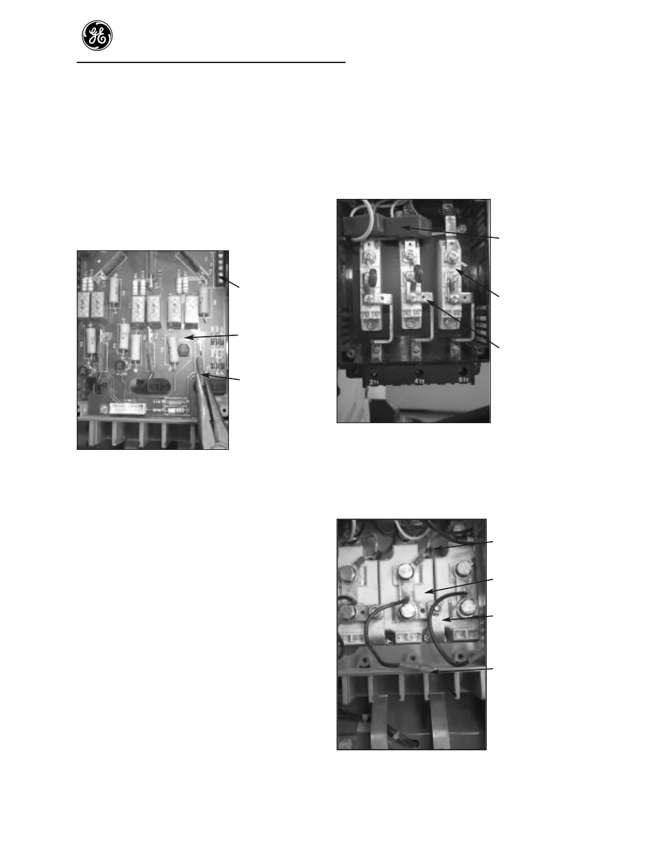
Protection Board (Figure 11). Note the
locations of these terminals for reassembly.
6- point Terminal
Board
Protection
Board
Wire connectors
Figure 11. Remove push on wire connectors
Step 16. Disconnect the 4 leads from the two current
transformers and the 2 leads from the
thermostat to the 6 -point Terminal Board
(TB) (located at the top right edge of the
Protection Board)(Figure 10). Label these
leads to assure connections are the same to
the 6- point terminal board on the new
Protection Board.
Step 17. Loosen the 4 screws holding the Protection
Board to the housing. Remove the Protection
Board from the ASTAT-CD Plus.
Step 18. Reassemble the new Protection Board, CT
leads, thermostat leads, screws, gate wires and
ground wire, Logic and Power Supply Board
assembly, screws and ribbon connectors in the
reverse order of the above listed disassembly
(steps 12 and 6).
Step 19. Reassemble the plastic cover, connectors and
sheet metal covers using step 7.
To replace SCR modules
NOTE: POWER MUST BE REMOVED
BEFORE SERVICING.
SCR disassembly instructions - Size J
Current
transformers
SCR modules
Bus bars
Figure 12. SCR module, MOV and bus bar
location (Size J)
SCR disassembly instructions -
Sizes L and M
MOV
SCR modules
Bus bars
Connectors to
Protection Board
Figure 13. SCR module, MOV and bus bar
location (Sizes L and M)