Astat-cd plus service instructions – GE Industrial Solutions ASTAT-CD Plus Solid-State Starters User Manual
Page 20
ASTAT-CD Plus Service Instructions
20
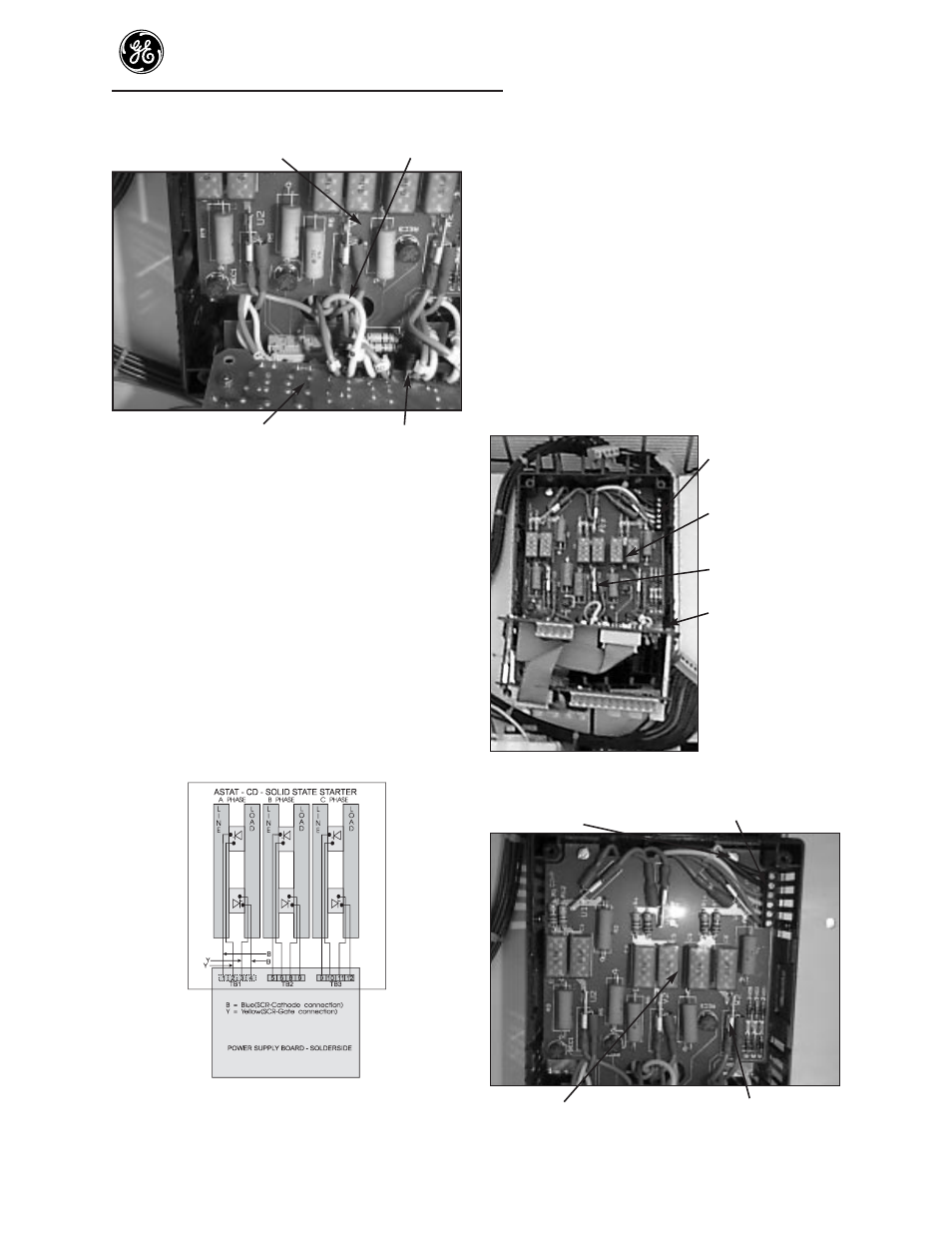
Protection Board
Gate leads
Bottom of Power Supply Board
Gate terminal board
Figure 6. Gate leads, Protection and Power
Supply Boards
Remove the Power Supply Board. Remove
the hex standoffs, nuts and washers from the
Power Supply Board for use on the
replacement board.
Step 15. Reassemble the standoffs to the new Power
Supply Board. Reconnect the gate wires to
the Power Supply Board (terminals 1 to 12)
and reinstall the 4 screws which hold the
Power Supply Board to the black plastic
housing. Refer to (Figure 7) for gate lead
connections.
Step 16. Reassemble the Logic Board, cover and
terminal connectors using steps 7-10.
Figure 7. Gate lead connections
Y = Yellow wire B = Blue wire
SCR pairs are to be twisted to reduce EMI (not shown in sketch).
To replace the Protection Board.
NOTE: POWER MUST BE REMOVED
BEFORE SERVICING.
Step 17. Remove the Cover, steps 1-3, and remove the
(Logic and Power Supply Board assembly) by
removing the 4 screws holding the Power
Supply Board to the black housing. If a
yellow/green wire is connected to the bottom
of the Power Supply Board, it must be
disconnected. Lower the Logic and Power
Supply Board assembly (Figure 8). Remove
the blue and yellow gate wires per steps 13
and 14.
6-point Terminal
Board
Protection Board
6 wire connectors
Power Supply and
Logic Board
assembly
Figure 8. Board location
Mounting Screw
6-point Terminal Board
Protector Board
Wire Connectors
Figure 9. Remove wire connectors