Astat-cd plus service instructions, Reassembly – GE Industrial Solutions ASTAT-CD Plus Solid-State Starters User Manual
Page 27
ASTAT-CD Plus Service Instructions
27
Step 19. Label the 4 leads from the two current
transformers and the 2 leads from the
thermostats to assure connections are the
same to the 6-point Terminal Board on the
new Protection Board. Disconnect the 4 leads
from the two current transformers and the 2
leads from the thermostats to the 6-point
Terminal Board (Figure 9).
Step 20. Loosen the mounting screws holding the
Protection Board to the housing. Remove the
Protection Board from the ASTAT-CD Plus.
Reassembly
Step 21. Reassemble the new Protection Board, the
push-on wire connectors, the CT leads,
thermostat leads, screws, gate wires and
ground wire (if used), Logic and Power
Supply Board assembly, screws and ribbon
connectors in the reverse order of the above
listed disassembly (Steps 16-20).
Step 22. Reassemble the plastic cover, connectors and
sheet metal cover using steps 8-10.
To replace SCRs
NOTE: POWER MUST BE REMOVED
BEFORE SERVICING.
Step 23. Remove the front cover by removing the (6)
Phillips head screws (Figure 1).
Step 24. Phase 1 or 3 - Remove bus bars, the fan
assembly, the top ventilating cover and the
heat sink insulator covers. Remove the
thermostat wires, gate and cathode leads from
the SCRs, current transformer leads from the
C. T. (only on Phase 1) and other parts that
interfere with removal of the SCR/heatsink
assembly (Figure 10).
Phase 2 - Remove bus bars, the fan assembly,
the top ventilating cover and the heat sink
insulator covers from phase 2 heatsink assembly
(the Control assembly is attached to the top
insulator cover - handle carefully). Remove (2)
thermostat wires from the thermostats, the gate
and cathode leads from the SCRs, current
transformer leads from the Phase 2 C. T, and
other parts that interfere with removal of the
Phase 2 SCR/heatsink assembly (Figure 10).
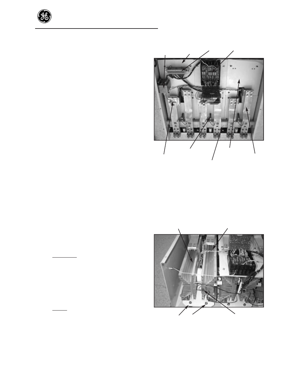
Blower Insulating Terminal Circuit
board
transformers
cover
board
assembly
Phase 1
Phase 2
Phase 3
MOV
Heatsink cover
Current transformer
Bus bar
Bus bar support bracket and fan assembly
Figure 10. Parts locations insulating covers
Step 25. Remove the bolts on the ends of the heatsink
assembly that hold the H. S. assembly to the
housing insulators. Then slide the H. S.
assembly out the bottom of that ASTAT
housing. (Figure 11). Retain all parts and
hardware for reassembly.
Heatsink assembly
SCR gate and cathode leads
Bolts holding heatsink
Thermostat
assembly to housing
Figure 11. SCR and heatsink location