Astat-cd plus service instructions, Reassembly – GE Industrial Solutions ASTAT-CD Plus Solid-State Starters User Manual
Page 16
ASTAT-CD Plus Service Instructions
16
Step 19. Disconnect the 4 leads from the two current
transformers and the 2 leads from the
thermostat to the 6- point Terminal Board
(Figure 8). Label these leads to assure
connections are the same to the 6- point
Terminal Board on the new Protection
Board.
Step 20. Loosen the 4 mounting screws holding the
Protection Board to the housing. Remove the
Protection Board from the ASTAT-CD Plus.
Reassembly
Step 21. Reassemble the new Protection Board, CT
leads, thermostat leads, screws, gate wires and
ground wire, Logic and Power Supply Board
assembly, screws and ribbon connectors in the
reverse order of the above listed disassembly
(Steps 17-20).
Step 22. Reassemble the plastic cover, connectors and
sheet metal covers using steps 8 - 10.
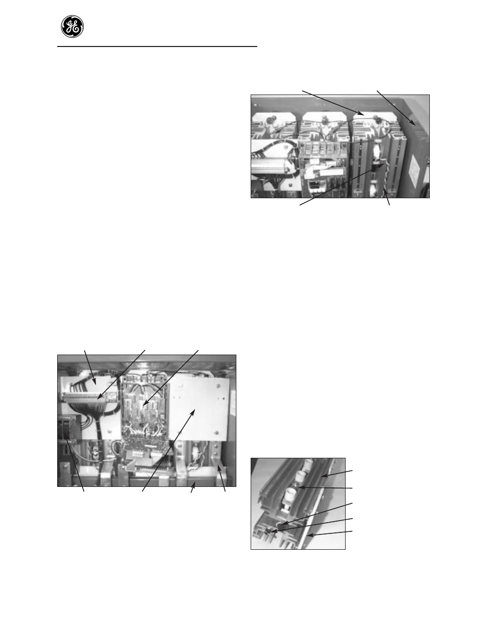
To replace SCRs
Insulating Terminal
Circuit
board
cover
board
assembly
Transformer
Heat sink
Bus bar support
Bus
(Sizes R & S only)
cover
bracket and
bar
fan assembly
Figure 10. Parts locations insulating cover
Bolts holding heatsink
assembly to housing
Steel housing
SCR and heatsink assembly
Gate and cathode leads
Figure 11. SCR and heatsink location
Step 23. Remove cover and circuit boards using
Steps 17-20.
Step 24. Remove bus bars, insulators, barriers, fan
assemblies, thermostat wires and other parts
that interfere with removal of the
SCR/heatsink assembly (Figure 10).
Step 25. Remove the SCR/heatsink assembly from the
ASTAT-CD Plus housing (Figure 11). Retain
all parts and hardware for reassembly.
Step 26. Remove MOVs, thermostat, mounting
insulator and other parts to allow disassembly
of the clamps and SCRs from the heatsinks
(Figure 12).
CAUTION: Do not adjust or move the preset nut
(6) (Figure 13). The preset nut (6) and the
belleville washers under the cross piece (5) are
preset to the required force for assembly and
clamping of the new SCR to the heatsink.
SCR and heatsink
assembly
Clamp assembly
MOV
Thermostat
Mounting plate
Figure 12. SCR and heatsink assembly