Astat-cd plus service instructions – GE Industrial Solutions ASTAT-CD Plus Solid-State Starters User Manual
Page 28
ASTAT-CD Plus Service Instructions
28
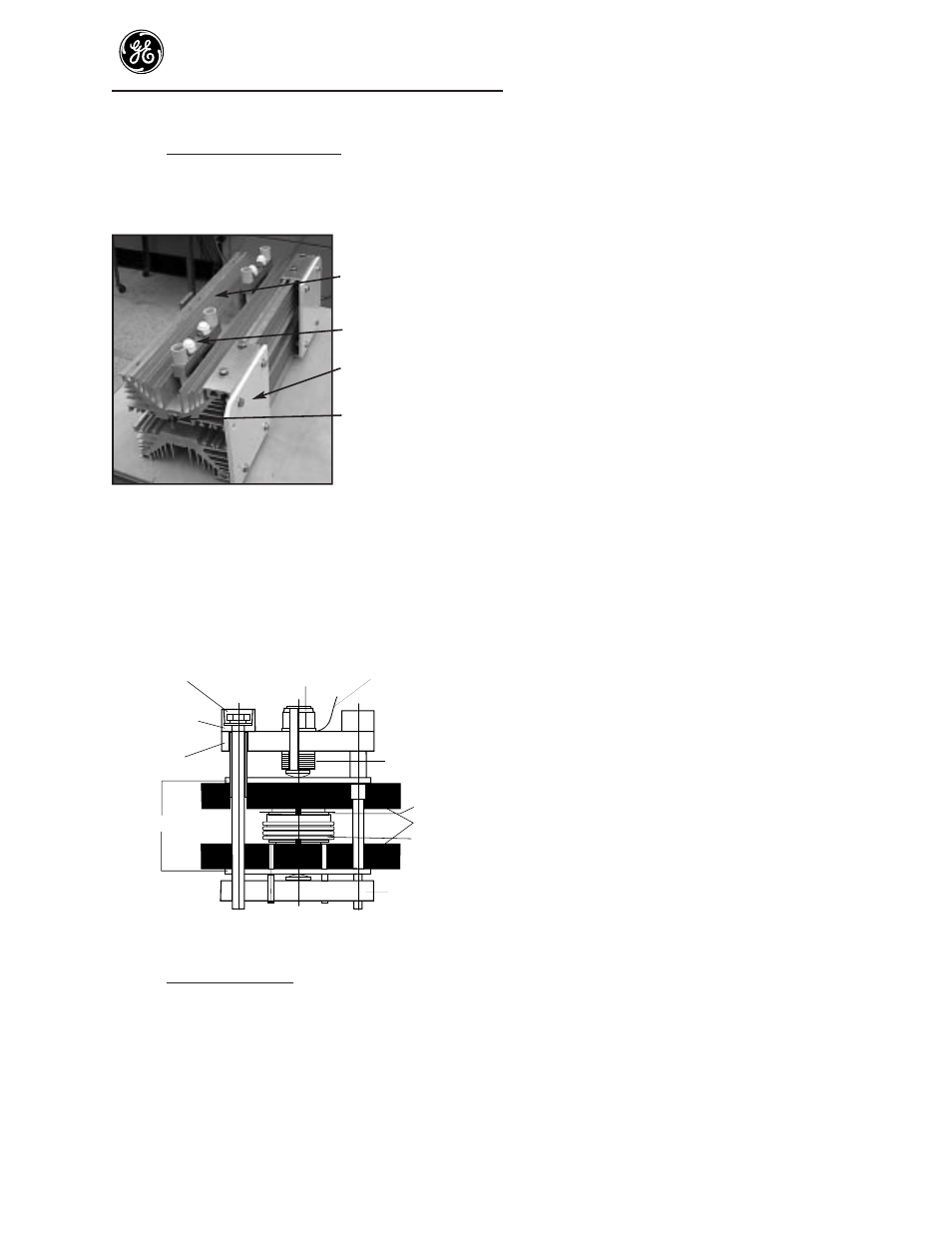
Step 26. SCR/Heat sink disassembly - Remove the
thermostat, mounting insulator and other
parts to allow disassembly of the clamps and
SCRs from the heatsinks (Figure 12).
SCR and heatsink
assembly
Clamp assembly
Mounting plate
Thermostat
Figure 12. SCR and heatsink assembly
CAUTION: Do not adjust or move the preset nut
(6) (Figure 13). The preset nut (6) and the bevel
washers under the cross piece (5) are preset to the
required force for assembly and clamping of the
new SCR to the heatsink.
Figure 13. SCR and heatsink assembly
Step 27. Removing the SCRs (Figure 13) - Loosen the
tension bolts (10) alternately, 1/4 turn at a
time, on each SCR until pressure releases on
the SCRs. Remove bolts and clamps to release
the heatsinks. Note: record the position of
both SCRs (gate and cathode connectors on
the SCR) for reassembly.
Caution: Do not adjust or move the pre-set nut (6)
(Figure 13). The pre-set nut and the bevel washers
under the cross piece (5) are pre-set to the required
force for assembly and clamping of the new SCR to
the heatsink.
Note: The mounting surface of the heatsink
must be flat and clean (i.e., bare metal) and
the SCR surface must be clean. Thermal
compound must be coated on all mating
surfaces between the SCR and the heatsink.
Step 28. Clean both heat sink surfaces with a fine
abrasive such as Scotch brite, then remove all
particles from the surface of the heatsinks. To
clean the SCR, wipe the SCR with a mild
solvent.
Step 29. Apply a light coat of thermal compound such
as Electrolube 2GX to both sides of the SCR
and to both heatsink surfaces that mate to the
SCR.
Step 30. Make sure that the orientation of the SCR is
correct(as disassembled) and place the
contact face of the SCR over the locating pin
in the mating heatsink surface. Twist the SCR
backward and forward by hand applying firm
pressure to the SCR. Remove the SCR from
the heatsink, the mating surfaces must be
uniformly coated with thermal compound. If
the mating surfaces are not coated evenly,
apply slightly more thermal compound to the
surfaces and twist back and forth as before.
Step 31. With the 2 SCRs located properly on the
heatsink, i.e. the gate and cathode terminals
on the SCR must be on the proper side of the
heatsink assembly (as disassembled), place
the other heatsink over the SCRs. Refer to
figure 13.
The clamp is assembled so that the cross
piece(5) with the pressure plate(4) and the
tension bolts (10) are at the top. Underneath
the cross piece (3) with the pressure plate (4)
is put in position and the two tension bolts
(10) are alternately tightened carefully until a
slight resistance is felt. Check that both cross
pieces (3) and (5) are parallel. For this check,
it is sufficient to check that the tension bolts
project equal distances beyond the cross
piece(3). The tension bolts (10) may now be
alternately tightened 1/4 turn at time until
10 Tension bolt
4 Pressure plates
5 Cross piece
6 Pre-set nut
8 Metal gauge
7 Belleville washers
3 Cross piece
9 Center pin
1 Heatsinks
2 SCR
11 Insulated sleeve