Astat-cd plus service instructions, Sizes n, q, r or s cover removal – GE Industrial Solutions ASTAT-CD Plus Solid-State Starters User Manual
Page 13
ASTAT-CD Plus Service Instructions
13
Carefully release the terminal connectors
from pins (Figure 2) and remove the
connectors (with wiring) from the starter.
Carefully pull the terminal connectors
straight off the ASTAT-CD Plus starter.
Step 3. Remove the plastic cover by using a flat-head
screwdriver to depress and release the plastic
tab on each side of the plastic cover (see
Figure 2 in Sizes F, G, H and I section).
To replace the Logic Board
Important: Always handle boards by
edges and do not distort parts on board.
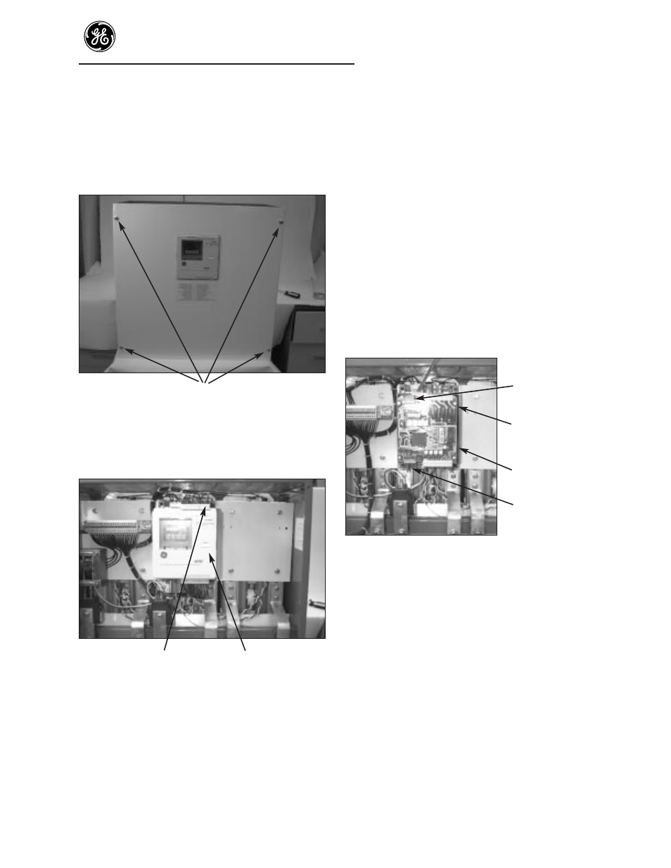
Step 4. The top printed circuit board is the Logic
Board.
Ribbon cable
Screw
Logic Board
Ribbon cable
Figure 3. Logic Board parts location
Step 5. To remove Logic Board, unplug the two
ribbon cables from the Logic Board.
Step 6. Remove the 4 corner screws holding the
Logic Board to the standoffs below the Logic
Board. Remove the Logic Board (Figure 3).
Step 7. Reassemble Logic Board to the starter. With
the display on the Logic Board at the upper
left corner, place the board on the standoffs
and attach the Logic Board in the reverse
order as listed in Steps 6 and 5 above. Make
sure the ribbon cable at the bottom of the
ASTAT is fully seated on both circuit boards
and that the ribbon cable will not interfere
with or touch the cover.
Sizes N, Q, R or S
Cover removal
NOTE: POWER MUST BE REMOVED
BEFORE SERVICING.
Screws
Figure 1. Cover screw locations
Step 1. Remove the front steel cover by removing the
4 Phillips screws (Figure 1).
Terminal connector
Cover
Figure 2. Terminal removal
Step 2. Remove the two 12- point plug-in terminal
connectors by inserting a flat- head
screwdriver between the terminal connectors
and that ASTAT-CD Plus cover (Figure 2).
Do not remove wiring from
terminal connectors.