Troubleshooting – GE Industrial Solutions MX150_MX250 Modbus Network Card User Manual
Page 26
■
■ 24
GE Zenith Controls ■
■
MX150/MX250 Series Modbus Network Card (71R-2200)
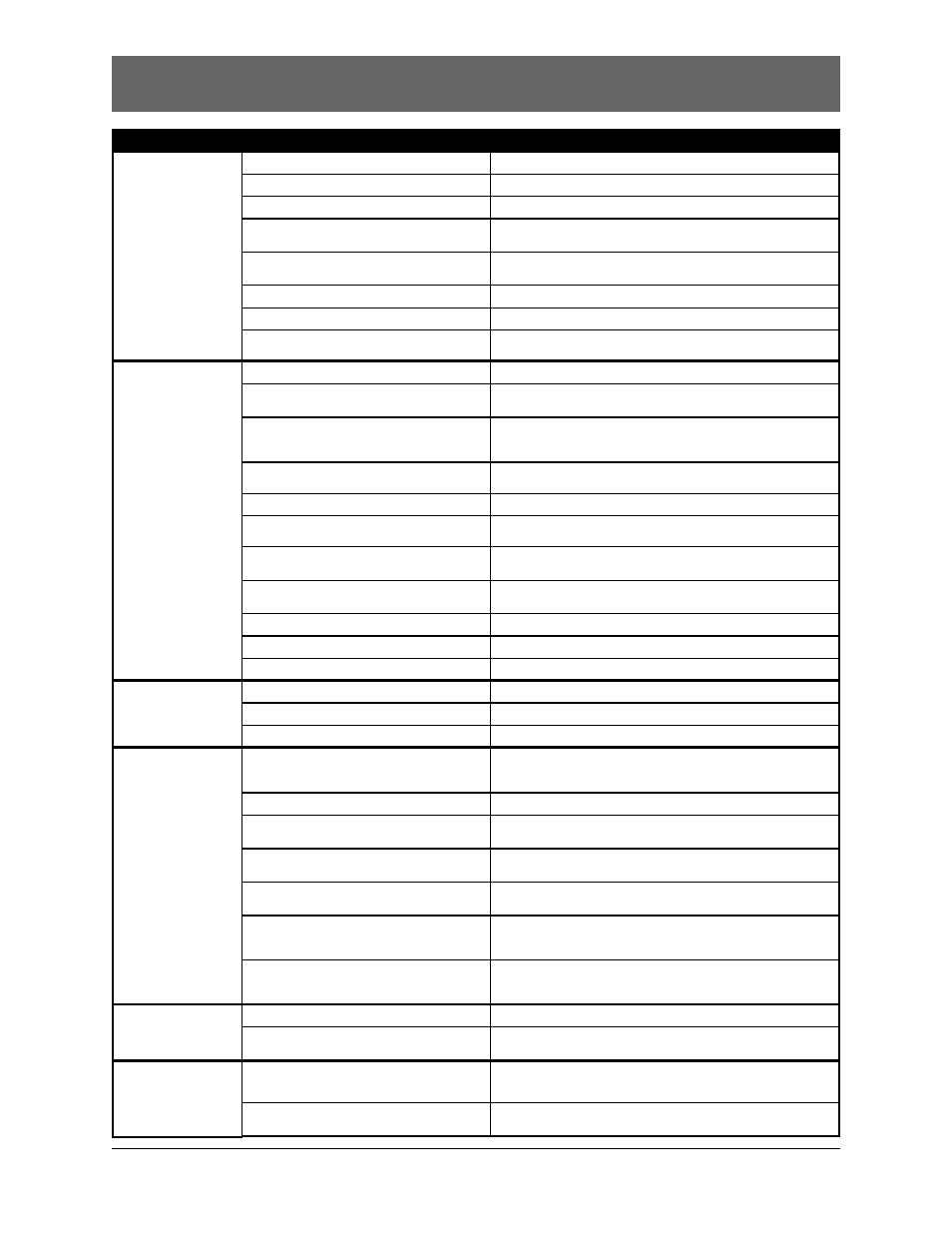
Troubleshooting
Problem
Possible Cause
Corrective Action
Trouble configuring
the Modbus card
Modbus card is not installed on the controller.
Install the Modbus card on the controller.
Controller does not have power.
Apply power to controller.
Configuration jumper, J4, is not installed.
Install the configuration jumper J4.
Wire between the RS232/485 converter
and Modbus card is not connected.
See Appendix D for the proper connections. Connect the
twisted pair wire between the converter and the Modbus card.
Polarity connections are incorrect.
Make sure that A & B on the Modbus card are connected to A & B
on the converter, respectively.
Wrong com port or baud rate.
Select the correct com port and baud rate. (Refer to Appendix D)
RS232/485 converter is not connected to the PC.
Connect the RS232/485 converter to the PC’s serial port.
No communications
between the Modbus
card and the Master
device
Controller does not have power.
Power up the controller.
Communicating with the wrong addressed slave.
Verify that the address on the Modbus card matches the address you
are communicating with. See Figure 2 for reference.
Network wire connection from the Master to the
Modbus card is broken or the wire is not connect-
ed to the Modbus card.
Check the wire connection from the Master to the Modbus card.
Connect the wire to the Network card if necessary.
Not using twisted pair wire to make
the network connection.
Make sure interconnect cable is a twisted pair wire (Belden 8471,
16 AWG) (GE Zenith Part # WMW-453).
Configuration jumper, J4, is still installed.
Remove the J4 configuration jumper.
Proper polarity markings are not being followed.
Make sure that A & B on the Modbus card are connected to A & B
on the converter, respectively.
Termination jumper, J6, is not installed
on the last slave in the chain.
Install termination jumper, J6, on the last slave in the chain.
Make sure no other devices have jumper J6 installed.
Modbus card is not installed on controller.
Install the Modbus card on controller.
Controller does not have power.
Power up the controller.
The Modbus card is damaged.
Call GE Zenith Controls Technical Support.
All LED’s on the
LED module are off.
Modbus card communication configuration
does not match the Master’s.
Verify that the Master and Modbus card have the same baud rate, data
bits, parity, stop bits with ASCII or RTU protocol selected.
Twisted pair wire length exceeds 4,000 ft.
Install repeater if wire length exceeds 4,000 ft.
RS485 multi-drop has more than 32 devices.
Install one repeater for every 32 devices on the network.
Controller network option not enabled.
Refer to Appendix H.
Illegal Data Value
exception response to
a write query
Data value being written is too high or too low.
Refer to Appendix B for maximum/minimum data ranges.
Data value would violate a minimum offset with
respect to another register.
Refer to Appendix B for minimum data offsets.
Slave Device Busy
exception response to
Modbus query
Controller has recently restarted after a power failure and
has not initialized the Modbus Card with new data yet.
Wait a few seconds for the controller to initialize
the Modbus Card with new data.
Controller is waiting for the In-Phase Monitor to
detect phase synchronization.
Refer to the “Operation with In-Phase Monitor” section of this manual
for more information.
Illegal Data Address
exception response
to a write query
Holding Register or Coil address is beyond the
legal range. There are no Holding Registers above
address 40232 and no Coils above address 128.
Make sure the correct address is being sent
Holding Register or Coil is Read Only.
Select a Holding Register or Coil that can be written.
Write Multiple Holding Register or Coil range
includes Read-Only registers.
Break up the write request into sections that contain only
Read/Write registers.
The feature associated with the register being
programmed is not enabled.
Enable the feature in the User Configuration Menu on the controller
HMI (if applicable), or call GE Zenith Controls Technical Support.
Writing non-zero data to nonprogrammable date
registers for CDP Exercisers.
Refer to the “Exerciser Time and Date Format” section of “Clock
Exercisers” for more information.
Writing CDP Exerciser registers with Write Single
Holding Register command, or Write Multiple
Holding Register command with invalid range.
Refer to the “Writing the Clock Exerciser Holding Registers” section for
more operation information.
Writing System Time registers with Write Single
Holding Register command, or Write Multiple
Holding Register command with invalid range.
Refer to the “Writing the System Time Holding Registers” section of
“System Time” for more information.
Attempting to configure the Modbus Card to ASCII
Mode, No Parity, and 1 Stop Bit.
The combination of ASCII Mode, No Parity, and 1 Stop Bit is not sup-
ported. Select another communication setting.