Appendix g, Modbus protocol illustration – GE Industrial Solutions MX150_MX250 Modbus Network Card User Manual
Page 21
■
■ GE Zenith Controls
19 ■
■
MX150/MX250 Series Modbus Network Card (71R-2200)
Appendix G
For a detailed specification of the Modbus protocol,
reference the Modicon website address
www.modbus.org.
The Modbus protocol provides the internal standard for
parsing messages. During communications on a Modbus
network, the protocol determines how each slave will
know its device address, recognize a message addressed
to it, determine the kind of action to be taken, and
extract any data or other information contained in the
message. If a reply is required, the slave will construct the
reply message and send it using Modbus protocol.
The following is a brief description of the Modbus com-
mands supported by the Modbus Network Card. Each
command consists of the following:
•
a sample query message that is sent out by the
master device to the designated slave
•
the slave’s reply message to the master device
The query and reply messages show how the information
is packeted and sent out using the Modbus Protocol.
Each query message consists of the following:
•
Slave Address – address of the slave you wish to
establish communications with.
•
Function Code – code that lets the slave know what
command is being requested, e.g. read coil,
write single coil.
•
Starting Address High/Low Order – high and low
byte of the address the master reads from or
writes to. Coils and Registers are addressed start-
ing at 0. For instance Coil 1 is address 0 and
Register 40001 is address 0.
•
Error Check Field – contains either a
CRC
(
RTU
mode) or
LRC
(
ASCII
mode) error check value.
The query message for specific functions requires some
of the following information:
•
Number of Data Points High/Low Order – high
and low byte of the number of addresses the
master wants to read.
•
Data High/Low Order – high and low byte of the
data that will be written to the slave device.
•
Number of Coils High/Low Order – high and low
byte for the number of coils to force
ON
or
OFF
.
•
Number of Regs High/Low Order – high and low
byte for the number of registers to preset.
•
Byte Count – is the number of data bytes which
are sent to the slave.
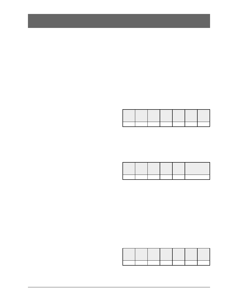
Slave
Address
05h
Figure G1 – Read Coil Status Query Message
Function
Code
Starting
Address
High Order
Starting
Address
Low Order
No. of Data
Points
High Order
No. of Data
Points
Low Order
Error
Check Field
(LRC or
CRC)
01h
00h
08h
00h
10h
—
Response
An example response to the Read Coil Status is shown
in Figure G2. The response includes the slave address,
function code, number of data bytes sent, the data,
and error checking.
The data consists of one bit per coil (1=
ON
, 0=
OFF
).
The status of coils 9-16 is C1 (hex) or 1100 0001 (binary).
Reading left to right, coils 16, 15, and 9 are
ON
and the
remainder is
OFF
. The other data byte is decoded similarly.
Slave
Address
05h
Figure G2 – Read Coil Status Response Message
Function
Code
Byte
Count
Data Coil
Status
9-16
Data Coil
Status
17-24
Error Check Field
(LRC or CRC)
01h
02h
C1h
A2h
—
Modbus Protocol Illustration
Read Coil Status (Function Code 01)
Query
This function allows the master device to obtain the
ON
/
OFF
bit status of various coils from the
addressed slave.
Figure G1 is a sample read coil status request to read
coils 9-24 (
MX
150/250 status bits) from slave device 5.
These query and reply messages are for both
RTU
and
ASCII
modes depending on whether the Error Check
Field contains a
CRC
or
LRC
respectively. Each value
in the query message is a hexadecimal value.
Read Holding Register (Function Code 03)
Read holding registers allows the master device to obtain
the binary contents of holding registers 4xxxx in the
addressed slave.
Query
Figure G3 is an example that reads registers
40006-40007 from slave 8.
Slave
Address
08h
Figure G3 – Read Holding Register Query Message
Function
Code
Starting
Address
High Order
Starting
Address
Low Order
No. of Data
Points
High Order
No. of Data
Points
Low Order
Error
Check Field
(LRC or
CRC)
03h
00h
05h
00h
02h
—