Appendix g, Modbus protocol illustration, Cont’d) – GE Industrial Solutions MX150_MX250 Modbus Network Card User Manual
Page 22: The requested, And a logical ‘0’ requests it to be, 00 hex) will set the coil, And the value zero will turn it, Coil 71, Hex) in slave device 17
■
■ 20
GE Zenith Controls ■
■
MX150/MX250 Series Modbus Network Card (71R-2200)
Write Multiple Coils (Function Code 15)
Forces each coil in a sequence of coils to either
ON
or
OFF
. The requested
ON
/
OFF
states are specified by con-
tents of the query data field. A logical ‘1’ in a bit position
of the field requests the corresponding coil to be
ON
and a
logical ‘0’ requests it to be
OFF
. Coils are addressed
starting at 0. For examples coil 1 is addressed as 0.
Query
The following example is a request to force a series of six-
teen coils starting at coil 41 (addressed as 40, or 28 hex)
in slave device 9.
The query data contents consist of two bytes: 3
C
9
B
hex
(0011 1100 1001 1011 binary). The binary bits corre-
spond to the coils in the following way:
The first byte sent (3
C
hex) addresses coils 41-48, with
the least significant bit addressing coil 41. The second
byte sent (9
B
hex) addresses coils 49-56, with the least
significant bit addressing coil 49.
Response
The slave responds with its address, function code, number
of data bytes, and the data. The contents of the registers
requested (data) are two bytes each. The first byte includes
the high order bits and the second, the low order bits.
Register 40006 , Normal Voltage Ph1-Ph2, has a value of
118 (76 hex) and register 40007, Normal Voltage Ph2-
Ph3 has a value of 120 (78 hex).
Appendix G
(cont’d)
Modbus Protocol Illustration
(cont’d)
Slave
Address
08h
Figure G4 – Read Holding Register Response Message
Function
Code
Byte
Count
High
Order
Data
Low
Order
Data
High
Order
Data
Error
Check Field
(LRC or CRC)
03h
04h
00h
76h
00h
—
Low
Order
Data
78h
Write Single Coil (Function Code 05)
This function forces a single coil either
ON
or
OFF
. A value
of 65,280 (
FF
00 Hex) will set the coil
ON
and the value
zero will turn it
OFF
; all other values are illegal and will not
affect that coil.
Query
Figure G5 is an example of a request to slave number 3
to turn
ON
coil 71.
Slave
Address
03h
Figure G5 – Write Single Coil Query Message
Function
Code
Starting
Address
High
Order
Starting
Address
Low
Order
Data
High
Order
Data
Low
Order
Error
Check Field
(LRC or
CRC)
05h
00h
46h
FF
h
00h
—
Response
The slave’s normal response to the Write Single Coil
query is to return the original message after the coil state
has been altered.
Slave
Address
03h
Figure G6 – Write Single Coil Response Message
Function
Code
Starting
Address
High
Order
Starting
Address
Low
Order
Data
High
Order
Data
Low
Order
Error
Check Field
(LRC or
CRC)
05h
00h
46h
FF
h
00h
—
Slave
Address
11h
Figure G7 – Write Single Holding Register Query Message
Function
Code
Starting
Address
High
Order
Starting
Address
Low
Order
Data
High
Order
Data
Low
Order
Error
Check Field
(LRC or
CRC)
06h
00h
28h
00h
5
C
h
—
Response
The slave’s response to the Write Single Holding
Register query is to return the original message after the
registers have been altered.
Slave
Address
11h
Figure G8 – Write Single Holding Register Response Message
Function
Code
Starting
Address
High
Order
Starting
Address
Low
Order
Data
High
Order
Data
Low
Order
Error
Check Field
(
LRC
or
CRC
)
06h
00h
28h
00h
5
C
h
—
Coil:
48 47 46 45 44 43 42 41
56 55 54 53 52 51 50 49
Bit:
0
0
1
1
1
1
0
0
1
0
0
1
1
0
1
1
Write Single Holding Register (Function Code 06)
This function allows the master to modify the contents
of one holding register.
Query
Figure G7 is an example of a request to preset register
40041 (Normal Pickup Voltage) to 92 (00 5
C
hex) in
slave device 17.
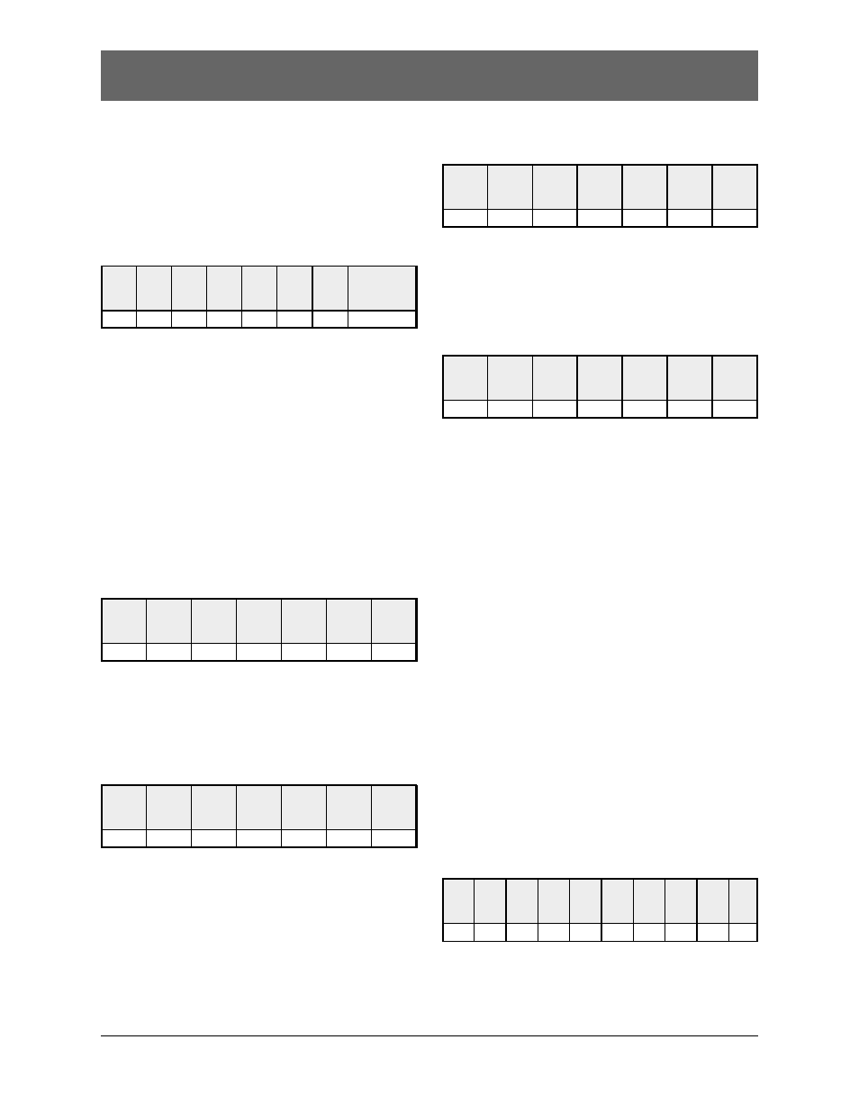
Slave
Address
09h
Figure G9 – Write Multiple Coils Query Message
Function
Code
0Fh
Starting
Address
High
Order
00h
Starting
Address
Low
Order
28h
Number
of Coils
High
Order
00h
Number
of Coils
Low
Order
10h
Byte
Count
02h
Data
High
Order
3
C
h
Data
Low
Order
9
B
h
Error
Check
Field
(
LRC
or
RC
)
–