B&B Electronics ZP9D-115RM-LR - Manual User Manual
Page 45
Manual Documentation Number: ZP9D-115RM-LR-0812
45
B&B Electronics Mfg Co Inc – 707 Dayton Rd - PO Box 1040 - Ottawa IL 61350 - Ph 815-433-5100 - Fax 815-433-5104 – www.bb-elec.com
B&B Electronics – Westlink Commercial Park – Oranmore, Galway, Ireland – Ph +353 91-792444 – Fax +353 91-792445 – www.bb-europe.com
• RB characters have been received by the UART
RB and RO criteria only apply to the first packet of a multi-packet transmission. If data
remains in the DI Buffer (UART receive) after the first packet, transmissions will
continue in a streaming manner until there is no data left in the DI Buffer.
When RO is the transmission-beginning criteria: The actual time between the
reception of the last character from the UART and the beginning of RF transmission
will be at least 800 µsec longer than the actual RO time to allow for transmission
setup. Additionally, it is subject to 100-200 µsec of additional uncertainty, which could
be significant for small values of RO at high UART bit rates.
The correct UART character time (10, 11, or 12 bits) is calculated based on the
following criteria:
• 1 start bit
• 8 data bits
• 0 or 1 parity bit [as determined by the NB (Parity) Command)
• 1 or 2 stop bits [as determined by SB (Stop Bits) Command]
RP (RSSI PWM Timer)
Command
used to enable a PWM ("Pulse
Width Modulation") output on the
Config/RSSI pin (pin 11 of the
OEM RF Module). The pin is
calibrated to show the difference
between received signal strength
and the sensitivity level of the RF module. PWM pulses vary from zero to 95 percent.
Zero percent means the received RF signal is at or below the published
sensitivity level of the module.
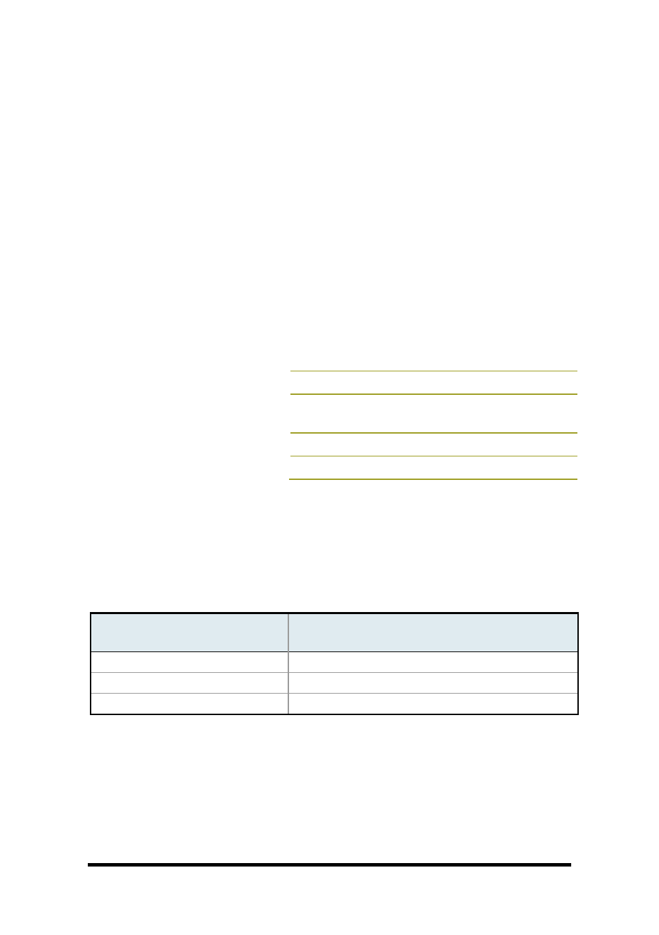
The following table shows dB levels above sensitivity and PWM values (The total time
period of the PWM output is 8.32 ms. PWM output consists of 40 steps and therefore
the minimum step size is 0.208 ms.):
PWM Values
dBm above sensitivity
PWM percentage (high period / total period)
10
20%
20
35%
30
50%
A non-zero value defines the time that PWM output is active with the RSSI value of
the last received RF packet. After the set time when no RF packets are received,
PWM output is set low (0 percent PWM) until another RF packet is received. PWM
output is also set low at power-up. A parameter value of 0xFF permanently enables
PWM output and always reflects the value of the last received RF packet.
The Config/RSSI pin is shared between PWM output and Config input. When the
module is powered, the Config pin is an input. During the power-up sequence, if RP
AT Command: ATRP
Binary Command: 0x22 (34 decimal)
Parameter Range: 0 - 0xFF [x 100 milliseconds]
Default Parameter Value: 0x20 (32d)
Number of bytes returned: 1