Selector guide – Rainbow Electronics MAX1329 User Manual
Page 73
MAX1329/MAX1330
12-/16-Bit DASs with ADC, DACs, DPIOs, APIOs,
Reference, Voltage Monitors, and Temp Sensor
______________________________________________________________________________________
73
Using the ADC with the ADC LT
(Less-Than) and GT (Greater-Than)
Digital Alarms
The ADC LT and GT alarms compare the latest ADC
result to the values programmed in the ADC LT Alarm
and ADC GT Alarm registers, if enabled, and assert the
appropriate GTA or LTA status bit in the Status register
once the threshold has been exceeded. The digital
alarms can be used as a safeguard during normal ADC
conversions to signify an event. Change the GT and LT
alarm thresholds, if needed, when selecting a new mux
input channel. The ADC can be put into autoconversion
mode to continuously convert without user intervention.
See the AUTO<2:0> bits in the
ADC Control Register
section to enable the auto mode and to program the
ADC conversion rate.
Layout, Grounding, and Bypassing
For best performance, use PCBs. Do not use wire-wrap
boards. Board layout should ensure that digital and ana-
log signal lines are separated from each other. Do not run
analog and digital (especially clock) signals parallel to
one another or run digital lines underneath the
MAX1329/MAX1330 package. High-frequency noise in
the V
DD
power supply can affect the MAX1329/MAX1330
performance. Bypass the AV
DD
and DV
DD
supplies with
a 0.1µF capacitor to GND, close to the AV
DD
and DV
DD
pins (see Table 32 for recommended capacitor values).
Minimize capacitor lead lengths for best supply-noise
rejection.
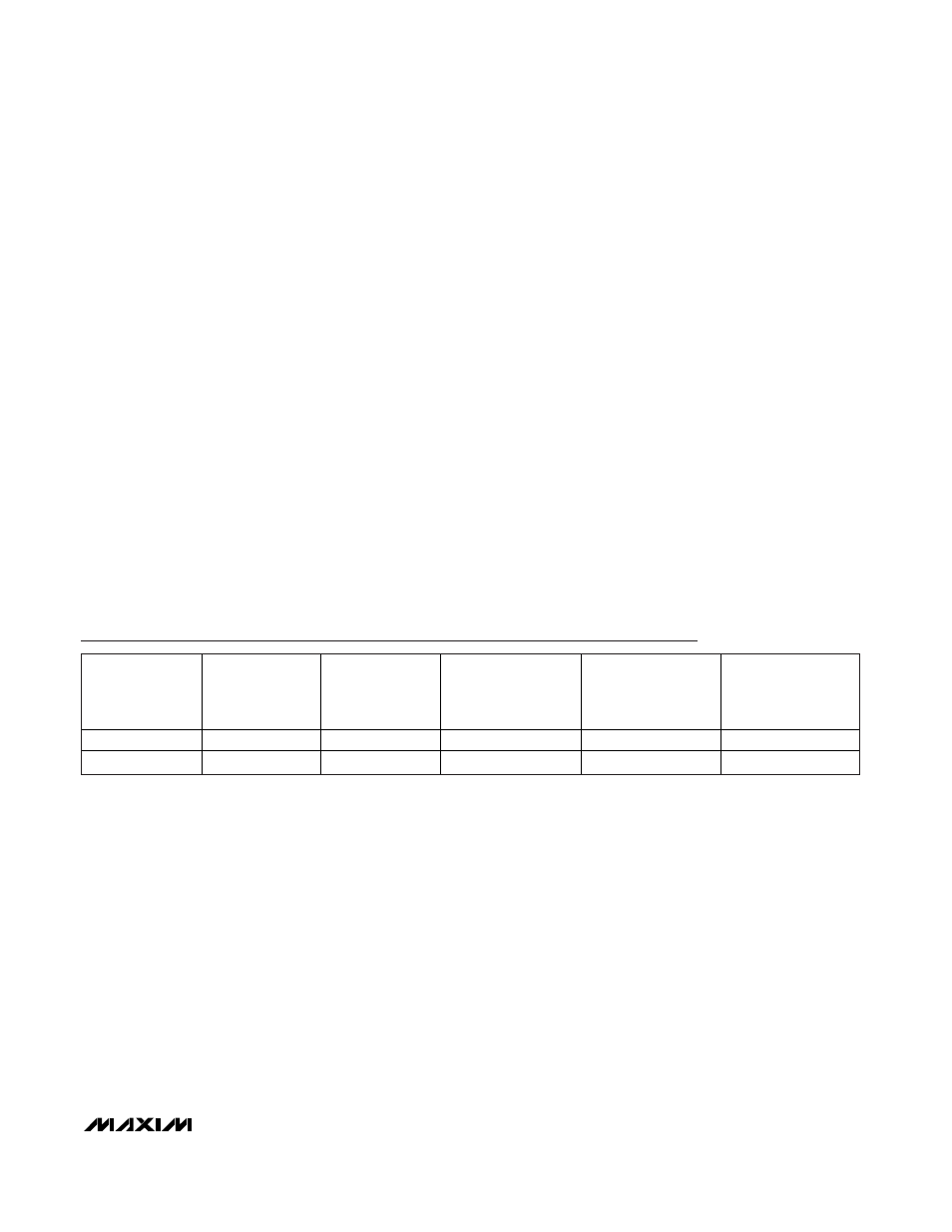
Selector Guide
PART
NO. OF DACS
NO. OF OP AMPS
TEMP SENSOR
ACCURACY (°C)
INTERNAL
REFERENCE TEMP
COEFFICIENT
(ppm/°C max)
TEMP
RANGE
MAX1329BETL+
2
1
±3
±75
-40°C to +85°C
MAX1330BETL+
1
2
±3
±75
-40°C to +85°C
+
Denotes a lead-free/RoHS-compliant package.