Rainbow Electronics MAX1329 User Manual
Page 35
MAX1329/MAX1330
12-/16-Bit DASs with ADC, DACs, DPIOs, APIOs,
Reference, Voltage Monitors, and Temp Sensor
______________________________________________________________________________________
35
The four conversion modes programmed by the
APD<1:0> and AUTO<2:0> bits in the ADC Control
register are: autoconvert, fast power-down, normal, and
burst modes. In normal and fast power-down modes,
single conversions are initiated with the ADC convert
command or by toggling a configured DPIO. In fast
power-down mode, the PGA and ADC power down
between conversions to reduce power. A minimum of
16 clock cycles is required to complete a conversion in
normal or fast power-down mode.
Burst mode is initiated with one ADC convert com-
mand and continuously converts on the same channel
sending the data directly to DOUT as long as there is
activity on SCLK and
CS is low. Burst mode aborts
when
CS goes high. In burst mode, SCLK directly
clocks the ADC. For best performance, synchronize
SCLK with the CLKIO clock (see Figure 18). A mini-
mum of 14 clock cycles is required to complete a con-
version in burst mode.
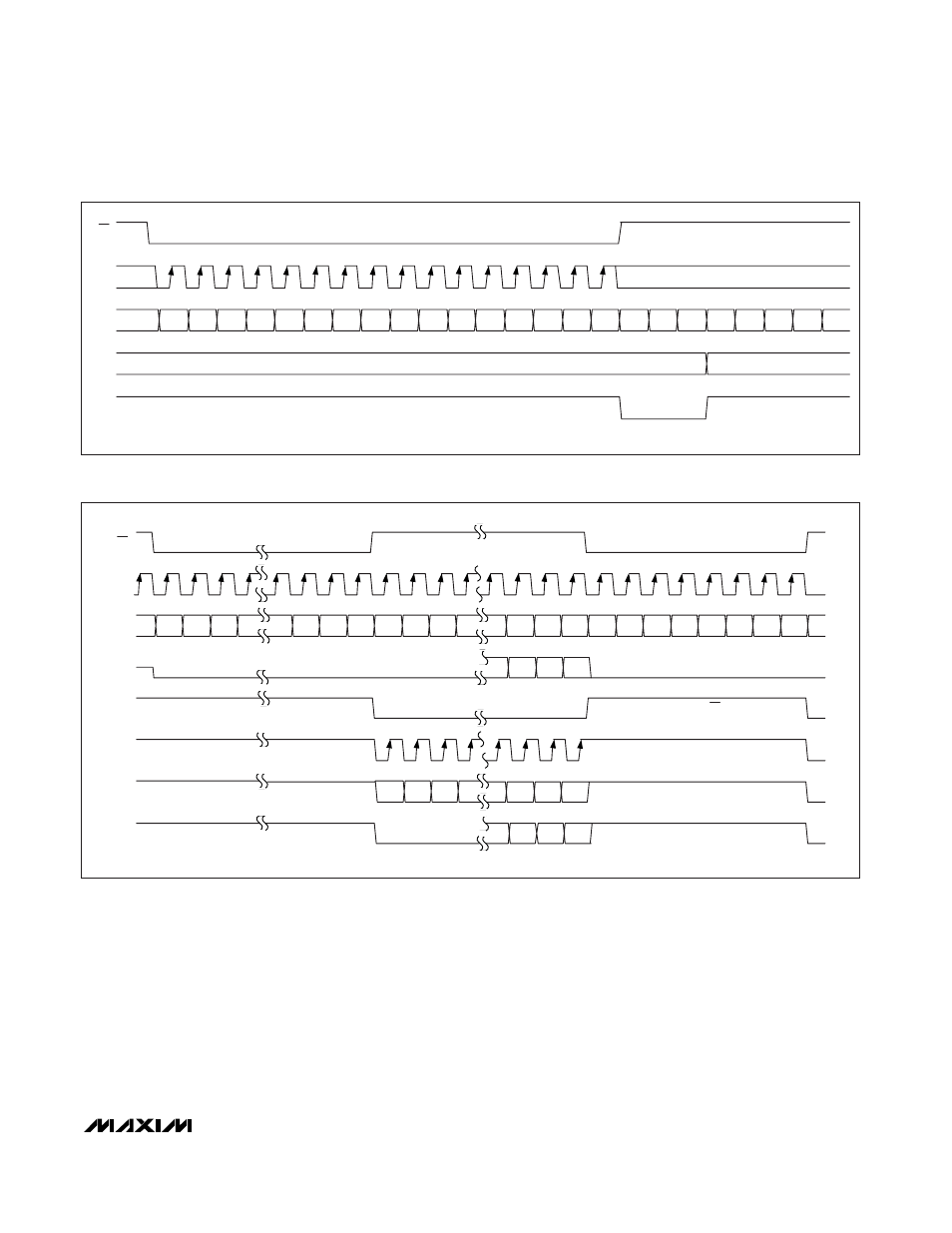
0
1
0
AB
D
11
SCLK
DIN
X
D
10
D
9
D
8
D
7
D
6
D
5
D
4
D
3
D
2
D
1
D
0
X
X
X
X
X
X
X
X
DAC
DPIO
PREVIOUS OUTPUT
NEW OUTPUT
RISING EDGE TRIGGERED
X = DON'T CARE.
CS
Figure 16. Write to DACA (AB = 0) or DACB (AB = 1) Input Register Followed by a DPIO DACA or DACB Load
D
N-1
D
2
D
1
D
0
E
N
D
2
D
1
SCLK
DIN
D
N
DOUT
X
X
X
D
7
D
6
D
5
D
4
D
3
X
D
N-2
D
N-3
D
3
E
N-1
E
N-2
E
N-3
E
3
E
2
E
1
E
0
D
0
APIO4
APIO3
APIO2
E
N
X
X
X
X
E
N-1
E
N-2
E
N-3
APIO1
E
3
E
2
E
1
E
0
WRITE TO MAX1329/MAX1330 TO
ENABLE SPI MODE
WRITE THROUGH MAX1329/MAX1330 TO
APIO DEVICE
NORMAL WRITE TO MAX1329/MAX1330
SET BY APIO CONTROL REGISTER
SET BY APIO CONTROL REGISTER
SET BY APIO CONTROL REGISTER
SET BY APIO CONTROL REGISTER
INVERTED CS
SET TO GPO
SET TO GPI
SET TO GPO
X = DON'T CARE.
CS
Figure 17. Write to Program and Use APIO SPI Mode