Rainbow Electronics MAX1329 User Manual
Page 62
MAX1329/MAX1330
12-/16-Bit DASs with ADC, DACs, DPIOs, APIOs,
Reference, Voltage Monitors, and Temp Sensor
62
______________________________________________________________________________________
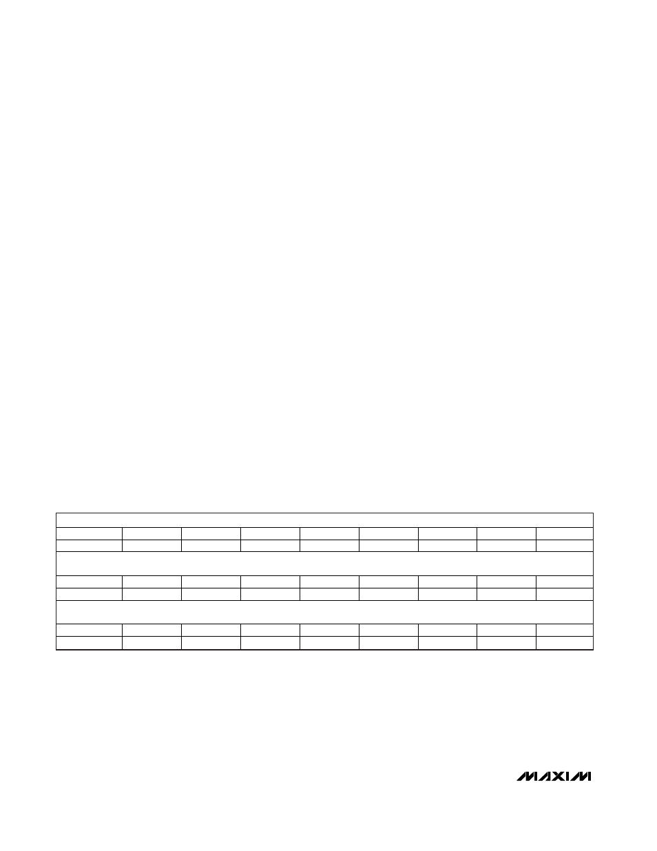
Interrupt Mask Register
The Interrupt Mask register bits enable the Status bits
to generate an interrupt on
RST1 and/or RST2 if pro-
grammed as interrupts (configured by VM1<1:0> in the
CP/VM Control register). Clearing a mask bit to 0
enables the corresponding bit in the Status register to
generate an interrupt. Setting a mask bit to 1 prevents
the Status bit from generating an interrupt. If the inter-
rupt output is asserted and another interrupt occurs,
the interrupt output remains asserted. Interrupt condi-
tions on
RST1 and/or RST2 are released after recogniz-
ing a read to the Status register. Updating of the Status
register is delayed until after the Status register has
been read. If the Status register read was aborted or if
a new unmasked Status bit is set during the read, the
interrupt output reasserts at the end of the read (see
Figure 15).
MV1A: 1.8V DV
DD
Voltage-Monitor Mask bit (default =
1). Set MV1A = 0 to unmask the VM1A Status bit to
generate an interrupt.
MV1B: 2.7V DV
DD
Voltage-Monitor Mask bit (default =
1). Set MV1B = 0 to unmask the VM1B Status bit to
generate an interrupt.
MVM2: AV
DD
Voltage-Monitor Mask bit (default = 1).
Set MVM2 = 0 to unmask the VM2 Status bit to gener-
ate an interrupt.
MADD: ADC Done Mask bit (default = 1). Set MADD = 0
to unmask the ADD Status bit to generate an interrupt.
MAFF: ADC FIFO Full Mask bit (default = 1). Set MAFF =
0 to unmask the AFF Status bit to generate an interrupt.
MACF: ADC Accumulator Full Mask bit (default = 1).
Set MACF = 0 to unmask the MACF Status bit to gener-
ate an interrupt.
MGTA: ADC GT Alarm Mask bit (default = 1). Set MGTA
= 0 to unmask the GTA Status bit to generate an interrupt.
MLTA: ADC LT Alarm Mask bit (default = 1). Set MLTA =
0 to unmask the LTA Status bit to generate an interrupt.
MAPR<4:1>: APIO Rising-Edge Mask bits (default =
1111). Set MAPR_ = 0 to unmask the corresponding
APIO_ Status bit to generate an interrupt.
MAPF<4:1>: APIO Falling-Edge Mask bits (default =
1111). Set MAPF_ = 0 to unmask the corresponding
APIO_ Status bit to generate an interrupt.
MDPR<4:1>: DPIO Rising-Edge Mask bits (default =
1111). Set MDPR_ = 0 to unmask the corresponding
DPIO_ Status bit to generate an interrupt.
MDPF<4:1>: DPIO Falling-Edge Mask bits (default =
1111). Set MDPF_ = 0 to unmask the corresponding
DPIO_ Status bit to generate an interrupt.
Reset Register
A write to the Reset register resets all registers to their
default values. A valid write consists of the 8-bit
address and 8 don’t-care bits of data. The reset occurs
on the 16th rising edge of SCLK.
MSB
NAME
MV1A
MV1B
MVM2
MADD
MAFF
MACF
MGTA
MLTA
DEFAULT
1
1
1
1
1
1
1
1
NAME
MAPR4
MAPR3
MAPR2
MAPR1
MAPF4
MAPF3
MAPF2
MAPF1
DEFAULT
1
1
1
1
1
1
1
1
LSB
NAME
MDPR4
MDPR3
MDPR2
MDPR1
MDPF4
MDPF3
MDPF2
MDPF1
DEFAULT
1
1
1
1
1
1
1
1