Rainbow Electronics MAX1329 User Manual
Page 65
MAX1329/MAX1330
12-/16-Bit DASs with ADC, DACs, DPIOs, APIOs,
Reference, Voltage Monitors, and Temp Sensor
______________________________________________________________________________________
65
Optical Reflectometry Application with
Dual LED and Single Photodiode
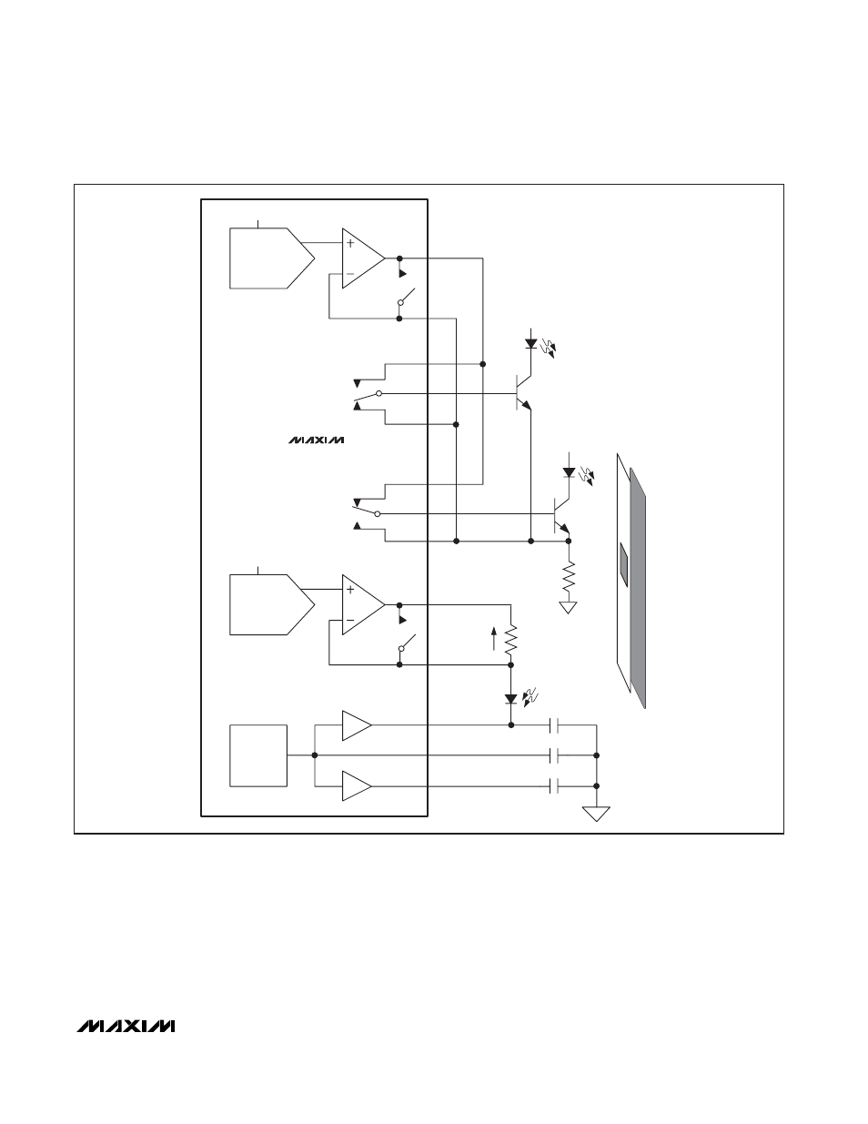
Figure 28 illustrates the MAX1329 in an optical reflectom-
etry application with two transmitting LEDs and one
receiving photodiode. The LEDs transmit light at specific
frequencies onto the sample strip and the photodiode
receives the reflections from the strip. Set the DACA out-
put to provide the appropriate bias currents for the LEDs.
The DSWA and DSWB switches are open in this configu-
ration. The LED bias current is calculated as I
LED
=
V
OUTA
/R
B
. REFADC is used as an analog ground and
DACB is set to ensure that the photodiode is not forward
biased. The I
F
current is converted to a voltage through
the R
F
resistor and measured by the internal ADC.
SPDT1 and SPDT2 are configured as single-pole
double-throw switches and enable switching between
V
BAT
PHOTO
DIODE
R
F
I
F
Q
1
DACA
OUTA
FBA
DACB
OUTB
FBB
SNO1
SNC1
SCM1
REFADC
REFDAC
REFADJ
2.5V
REF
A
V
= 0.5, 0.82, 1
REFDAC
REFDAC
SNC2
SNO2
SCM2
V
BAT
R
B
Q
2
LED
LED
1.25V
2.50V
A
V
= 0.5, 0.82, 1
DSWA
DSWB
SPDT1
SPDT2
1
μF
0.01
μF
1
μF
MAX1329
Figure 28. Optical Reflectometry Application with Dual LED and Single Photodiode