Table 16. dac reference buffer bit configuration – Rainbow Electronics MAX1329 User Manual
Page 50
MAX1329/MAX1330
12-/16-Bit DASs with ADC, DACs, DPIOs, APIOs,
Reference, Voltage Monitors, and Temp Sensor
50
______________________________________________________________________________________
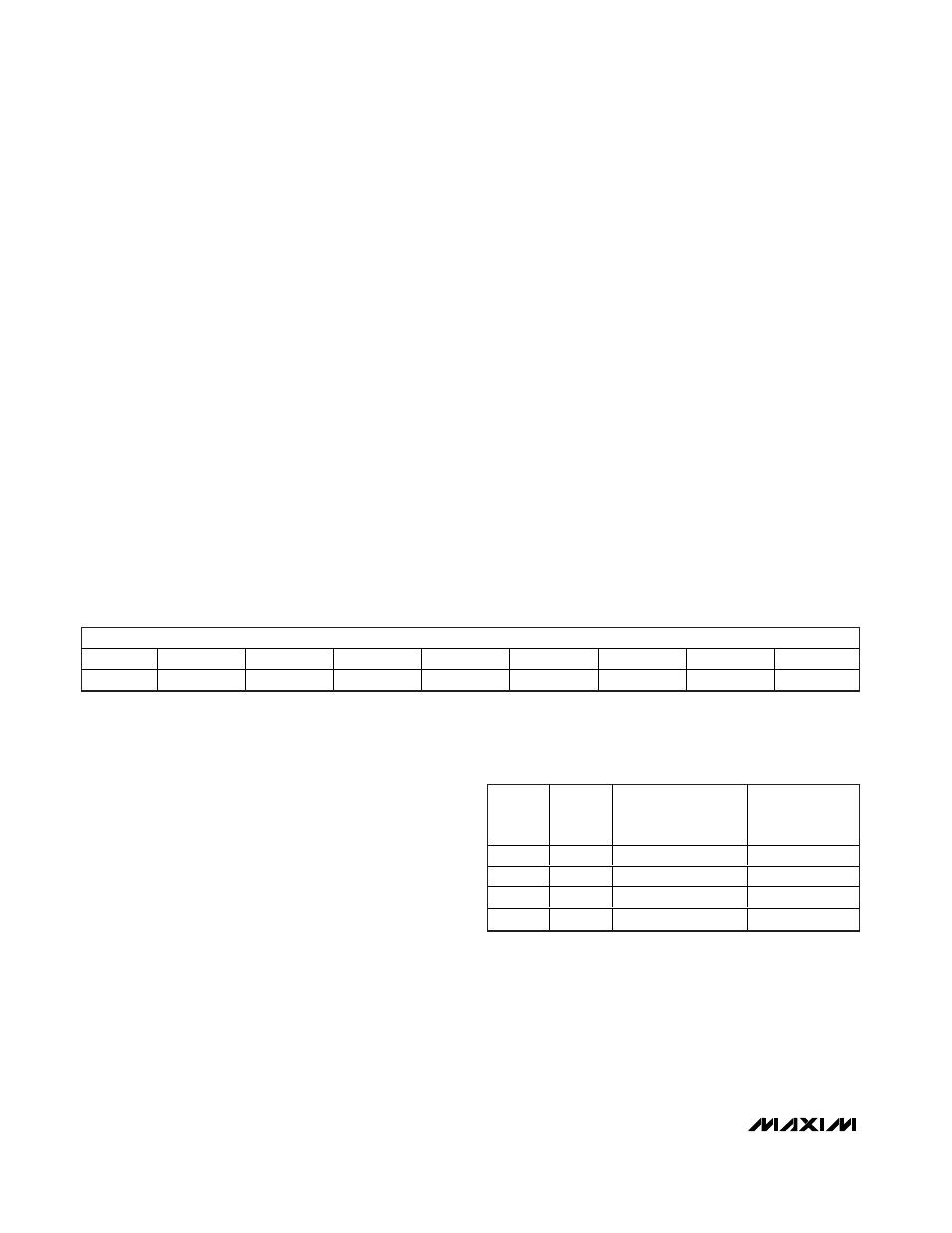
FIFOA Control Register
The FIFOA Control register enables the DACA FIFO,
configures the bipolar, symmetry, and continuous
modes, and sets the depth of the FIFO. Any change to
the contents of this register resets the FIFOA sequence
to the starting location. If the FIFO operation is enabled
(FFAE = 1), the next sequence command transfers the
DACA input register data to the output register. The
DACA input or output register can be written to when
the FIFO is enabled without affecting the FIFOA
sequence, but the DACA output and/or input register
data is changed.
FFAE: DACA FIFO Enable bit (default = 0). Set FFAE = 1
to enable the sequencing function. FFAE must be set to
0 to write to the FIFO. Writes to the FIFO when FFAE = 1
are ignored.
BIPA: DACA FIFO Bipolar bit (default = 0). Set BIPA = 0
to generate a unipolar waveform or set BIPA = 1 to gen-
erate a bipolar waveform. For a unipolar waveform, the
FIFOA data is added to the DACA input register data
during phases 1 and 2 (see Figures 8 and 9).
For a bipolar waveform, the FIFOA data is added to the
DACA input register data (during phases 1 and 2) and
subtracted from the DACA input register data (during
phases 3 and 4).
SYMA: DACA FIFO Symmetry bit (default = 0). Set
SYMA = 0 to generate an asymmetrical waveform, con-
sisting of phase 1 (BIPA = 0) or phases 1 and 4 (BIPA
= 1). Set SYMA = 1 to generate symmetry phases 1
and 2 (BIPA = 0) or phases 1–4 (BIPA = 1).
CONA: DACA FIFO Continuous bit (default = 0). Set
CONA = 0 to generate a single waveform or set CONA
= 1 to generate a periodic or continuous waveform.
DPTA<3:0>: DACA FIFO Depth bits (default = 0000).
The DPTA<3:0> bits set the depth of the FIFOA data
register to be used for waveform generation (see Table
17). The entire FIFOA data register can be filled with 16
words but only the number programmed by
DPTA<3:0> are used. During waveform generation, the
FIFOA words are added to the DACA input register
value before being sent to the DACA output register.
The first output is the DACA input register value. The
following value is the DACA input register value
summed with the FIFOA location 1 value. The FIFOA
locations are incremented until the FIFO depth speci-
fied by the DPTA<3:0> bits has been reached.
Table 16. DAC Reference Buffer Bit
Configuration
DREF1
DREF0
DAC REFERENCE
BUFFER GAIN (V/V)
(REFE = 0)
REFDAC
VOLTAGE (V)
(REFE = 1)
0
0
N/A
Buffer disabled
0
1
0.5
1.25
1
0
0.8192
2.048
1
1
1.0
2.5
MSB
LSB
NAME
FFAE
BIPA
SYMA
CONA
DPTA3
DPTA2
DPTA1
DPTA0
DEFAULT
0
0
0
0
0
0
0
0