Rainbow Electronics MAX1329 User Manual
Page 37
MAX1329/MAX1330
12-/16-Bit DASs with ADC, DACs, DPIOs, APIOs,
Reference, Voltage Monitors, and Temp Sensor
______________________________________________________________________________________
37
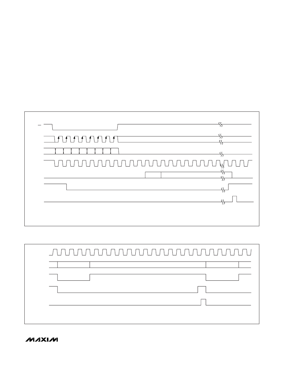
Once configured, autoconvert mode initiates with one
ADC Convert command. Conversions continue at the
rate selected by the ADC Autoconvert bits (see Table 4)
until disabled by writing to the ADC Control register. The
Autoconvert mode can run only in the normal or fast
power-down modes. The autoconvert function must be
disabled to use burst mode or DPIO CONVST mode.
When writing to the ADC Control register in fast power-
down mode with autoconvert disabled, acquisition
begins on the 1st rising ADC clock edge after
CS tran-
sitions high, and ends after the programmed number of
clock cycles. The conversion completes a minimum 14
clock cycles after acquisition ends. When autoconvert
is enabled, an additional three ADC clock cycles are
added prior to acquisition to allow the ADC to wake up.
See Figures 19 and 20 for timing diagrams.
1
M3
M2
M1
M0
G1
G0
BIP
SCLK
DIN
X
1
2
3
6
7
8
4
5
TRACK
CONVERT
ADC MODE
ADCDONE**
1
2
3
6
7
8
9
10
11
12
13
18
19
4
5
CLKIO
PD*
*PD IS AN INTERNAL SIGNAL. WHEN PD IS HIGH, THE ADC IS POWERED DOWN.
**ADCDONE IS AN INTERNAL SIGNAL. RISING EDGE ADCDONE SETS THE ADD BIT IN THE STATUS REGISTER.
X = DON'T CARE.
CS
Figure 20. Write Command to Start ADC Normal or Fast Power-Down, with Autoconvert Enabled and Conversions Clocked by CLKIO
(OSCE = 0, ADDIV<1:0> = 00, CLKIO<1:0> = 11)
CLKIO
ADC MODE
DPIO (CONVST)
CONVERT
CONVERT
EDGE TRIGGERED
TRACK
TRACK
1
2
3
4
5
6
7
8
9
10
11
12
13
14
15
16
17
18
19
20
21
22
23
PD*
ADCDONE**
*PD IS AN INTERNAL SIGNAL. WHEN PD IS HIGH, THE ADC IS POWERED DOWN.
**ADCDONE IS AN INTERNAL SIGNAL. RISING EDGE ADCDONE SETS THE ADD BIT IN THE STATUS REGISTER.
ADDIV = 00.
Figure 21. DPIO-Controlled ADC Conversion Start