Table 24. daca switch control configuration, Table 25. dacb switch control configuration – Rainbow Electronics MAX1329 User Manual
Page 55
MAX1329/MAX1330
12-/16-Bit DASs with ADC, DACs, DPIOs, APIOs,
Reference, Voltage Monitors, and Temp Sensor
______________________________________________________________________________________
55
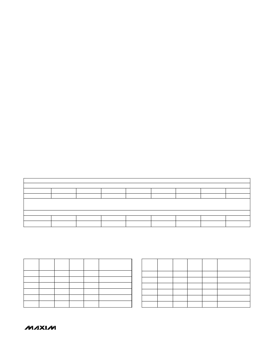
MAX1329
MSB
LSB
NAME
DSWA
DSWB
OSW1
X
SPDT11
SPDT10
SPDT21
SPDT20
DEFAULT
0
0
0
X
0
0
0
0
MAX1330
MSB
LSB
NAME
DSWA
X
OSW1
OSW2
SPDT11
SPDT10
SPDT21
SPDT20
DEFAULT
0
X
0
0
0
0
0
0
X = Don’t care.
Switch Control Register
The Switch Control register controls the two SPDT
switches and the feedback switches for DACA, DACB,
op amp 1, and op amp 2. The switches are controlled
through the serial interface or by a configured DPIO.
DSWA: DACA Switch Control bit (default = 0). The
DSWA bit controls the state of the DACA switch. A
logic-high in DSWA or on any DPIO_ configured as a
DACA switch control input causes the DACA switch to
close. The switch remains open when DSWA = 0 and
all DPIO_ pins configured as DACA switch control
inputs are logic-low. DPIO_ pins not configured as
DACA switch control inputs are treated as logic zeros.
See Table 24.
DSWB (MAX1329 only): DACB Switch Control bit
(default = 0). A logic-high in DSWB or an any DPIO_
configured as a DACB switch control input causes the
DACB switch to close. The switch remains open when
DSWB = 0 and all DPIO_s configured as DACB switch
control inputs are logic-low. DPIO_s not configured as
DACB switch control inputs are treated as logic zeros.
See Table 25.
OSW1: Op Amp 1 Switch Control bit (default = 0). The
OSW1 bit and DPIO_ configured in OSW1 mode control
the state of the op amp 1 switch. If DPIO_ is not config-
ured for OSW1 mode, it is set to 0 as shown in Table 26.
OSW2 (MAX1330 only): Op Amp 2 Switch Control bit
(default = 0). The OSW2 bit and DPIO_ configured in
OSW2 mode control the state of the op amp 2 switch. If
DPIO_ is not configured for OSW2 mode, it is set to 0
as shown in Table 27.
SPDT1<1:0>: Single-Pole, Double-Throw Switch 1
(SPDT1) Control bits (default = 00). The SPDT1<1:0>
bits and DPIO_ configured for SPDT1 mode control the
state of the switch. If DPIO_ is not configured for SPDT1
mode, it is set to 0 as shown in Table 28.
SPDT2<1:0>: Single-Pole, Double-Throw Switch 2
(SPDT2) Control bits (default = 00). The SPDT2<1:0>
bits and DPIO_ configured for SPDT2 mode control the
state of the switch. If DPIO_ is not configured for SPDT2
mode, it is set to 0 as shown in Table 29.
Table 24. DACA Switch Control
Configuration
DSWA
BIT
DPIO4
DPIO3 DPIO2 DPIO1
DACA SWITCH
STATE (DSWA)
0
0
0
0
0
Open
X
X
X
X
1
Closed
X
X
X
1
X
Closed
X
X
1
X
X
Closed
X
1
X
X
X
Closed
1
X
X
X
X
Closed
X = Don’t care.
Table 25. DACB Switch Control
Configuration
DSWB
BIT
DPIO4
DPIO3 DPIO2 DPIO1
DACB SWITCH
STATE (DSWB)
0
0
0
0
0
Open
X
X
X
X
1
Closed
X
X
X
1
X
Closed
X
X
1
X
X
Closed
X
1
X
X
X
Closed
1
X
X
X
X
Closed
X = Don’t care.