Table 17. daca fifo depth bit configuration – Rainbow Electronics MAX1329 User Manual
Page 51
MAX1329/MAX1330
12-/16-Bit DASs with ADC, DACs, DPIOs, APIOs,
Reference, Voltage Monitors, and Temp Sensor
______________________________________________________________________________________
51
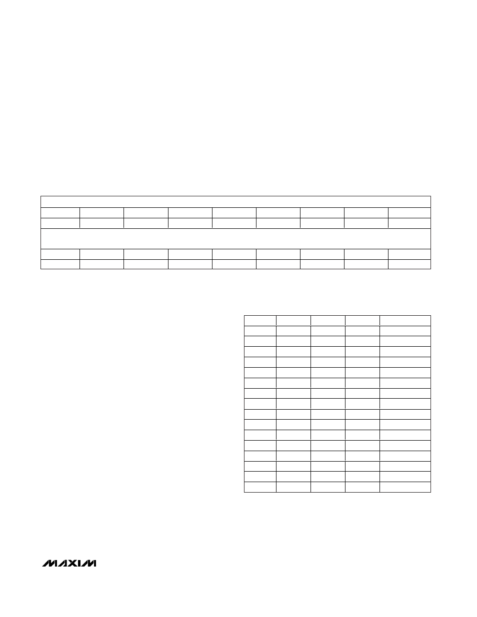
FIFOA Data Register
The FIFOA Data register stores up to 16 12-bit words that
can be used by DACA to generate a waveform.
FFADATA<11:0>: FIFOA Data bits (default = 0xXXX).
FFADATA<11:0> represents a 12-bit word that is left
justified with 4 don’t-care LSBs. A write or read opera-
tion always starts at location 1 and ends at the full FIFO
depth. Any attempt to write past the full FIFO depth
does not overwrite the data just written. Any attempt to
read past the full FIFO depth returns zeroes on DOUT.
A write to the FIFOA Data register is possible only when
the FFAE bit in the FIFOA Control register is 0. If FFAE
= 1, any write to the FIFOA Data register is ignored. A
read command is possible at any time. If BIPA = 0, the
data is interpreted as binary (0 to 4095). If BIPA = 1,
the data is interpreted as sign magnitude (-2047 to
+2047). In sign magnitude, the MSB represents the
sign bit, where 0 indicates a positive number and 1
indicates a negative number. The 11 LSBs provide the
magnitude in sign magnitude.
Table 17. DACA FIFO Depth Bit
Configuration
DPTA3
DPTA2
DPTA1
DPTA0
FIFOA DEPTH
0
0
0
0
1
0
0
0
1
2
0
0
1
0
3
0
0
1
1
4
0
1
0
0
5
0
1
0
1
6
0
1
1
0
7
0
1
1
1
8
1
0
0
0
9
1
0
0
1
10
1
0
1
0
11
1
0
1
1
12
1
1
0
0
13
1
1
0
1
14
1
1
1
0
15
1
1
1
1
16
MSB
NAME
FFADATA11
FFADATA10
FFADATA9
FFADATA8
FFADATA7
FFADATA6
FFADATA5
FFADATA4
DEFAULT
0
0
0
0
0
0
0
0
LSB
NAME
FFADATA3
FFADATA2
FFADATA1
FFADATA0
X
X
X
X
DEFAULT
0
0
0
0
X
X
X
X
X = Don’t care.