Rainbow Electronics MAX1329 User Manual
Page 58
MAX1329/MAX1330
12-/16-Bit DASs with ADC, DACs, DPIOs, APIOs,
Reference, Voltage Monitors, and Temp Sensor
58
______________________________________________________________________________________
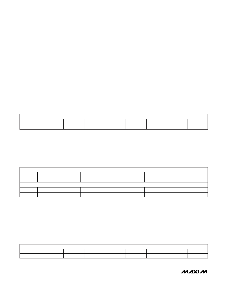
APIO Setup Register
The APIO Setup register programs the resistor pullup
and the logic level for APIO1–APIO4.
AP<4:1>PU: APIO Resistor Pullup bits (default = 1111).
AP_PU controls the internal 500kΩ (typ) pullup resistor
on the corresponding APIO_. AP_PU = 0 disables the
pullup resistor and AP_PU = 1 connects the pullup
resistor to AV
DD
. The pullup resistor is active only when
the corresponding APIO_ is configured as an input.
AP<4:1>LL: APIO Logic-Level bits (default = 0000). If
APIO_ is programmed as a GPO, set the corresponding
AP_LL = 0 to set APIO_ to a logic-low level or set AP_LL
= 1 to set APIO_ to a logic-high level. A read from AP_LL
returns the logic level at the corresponding APIO_ when
the register is read, regardless of the APIO mode.
DPIO Control Register
The Digital Programmable Input/Output (DPIO) Control
register programs the modes of the DPIO1–DPIO4.
DPIO1–DPIO4 are referenced to DV
DD
and DGND (see
Digital I/O in the
Electrical Characteristics
table).
DP_MD<3:0>: DPIO_ Mode Configuration bits (default
= 0000). DP_MD<3:0> configures the corresponding
DPIO_ (see Table 31).
DPIO Setup Register
The DPIO Setup register configures the pullup resistor
and logic level on DPIO1–DPIO4.
DP<4:1>PU: DPIO Resistor Pullup bits (default = 1111).
DP_PU controls the internal 500kΩ (typ) pullup resistor
on the corresponding DPIO_. DP_PU = 0 disables the
pullup resistor and DP_PU = 1 connects the pullup
resistor to DV
DD
. The pullup resistor is active only when
the corresponding DPIO_ is configured as an input.
DP<4:1>LL: DPIO Logic-Level bits (default = 0000). If
DPIO_ is programmed as a GPO, set the correspond-
ing DP_LL = 0 to set DPIO_ to a logic-low level or set
DP_LL = 1 to set DPIO_ to a logic-high level. A read
from DP_LL returns the logic level at the corresponding
DPIO_ when the register is read, regardless of the
DPIO mode.
MSB
LSB
NAME
DP4PU
DP3PU
DP2PU
DP1PU
DP4LL
DP3LL
DP2LL
DP1LL
DEFAULT
1
1
1
1
0
0
0
0
MSB
LSB
NAME
AP4PU
AP3PU
AP2PU
AP1PU
AP4LL
AP3LL
AP2LL
AP1LL
DEFAULT
1
1
1
1
0
0
0
0
MSB
NAME
DP4MD3
DP4MD2
DP4MD1
DP4MD0
DP3MD3
DP3MD2
DP3MD1
DP3MD0
DEFAULT
0
0
0
0
0
0
0
0
LSB
NAME
DP2MD3
DP2MD2
DP2MD1
DP2MD0
DP1MD3
DP1MD2
DP1MD1
DP1MD0
DEFAULT
0
0
0
0
0
0
0
0