Pin description (continued) – Rainbow Electronics MAX3541 User Manual
Page 9
MAX3541
Complete Single-Conversion
Television Tuner
_______________________________________________________________________________________
9
PIN
NAME
DESCRIPTION
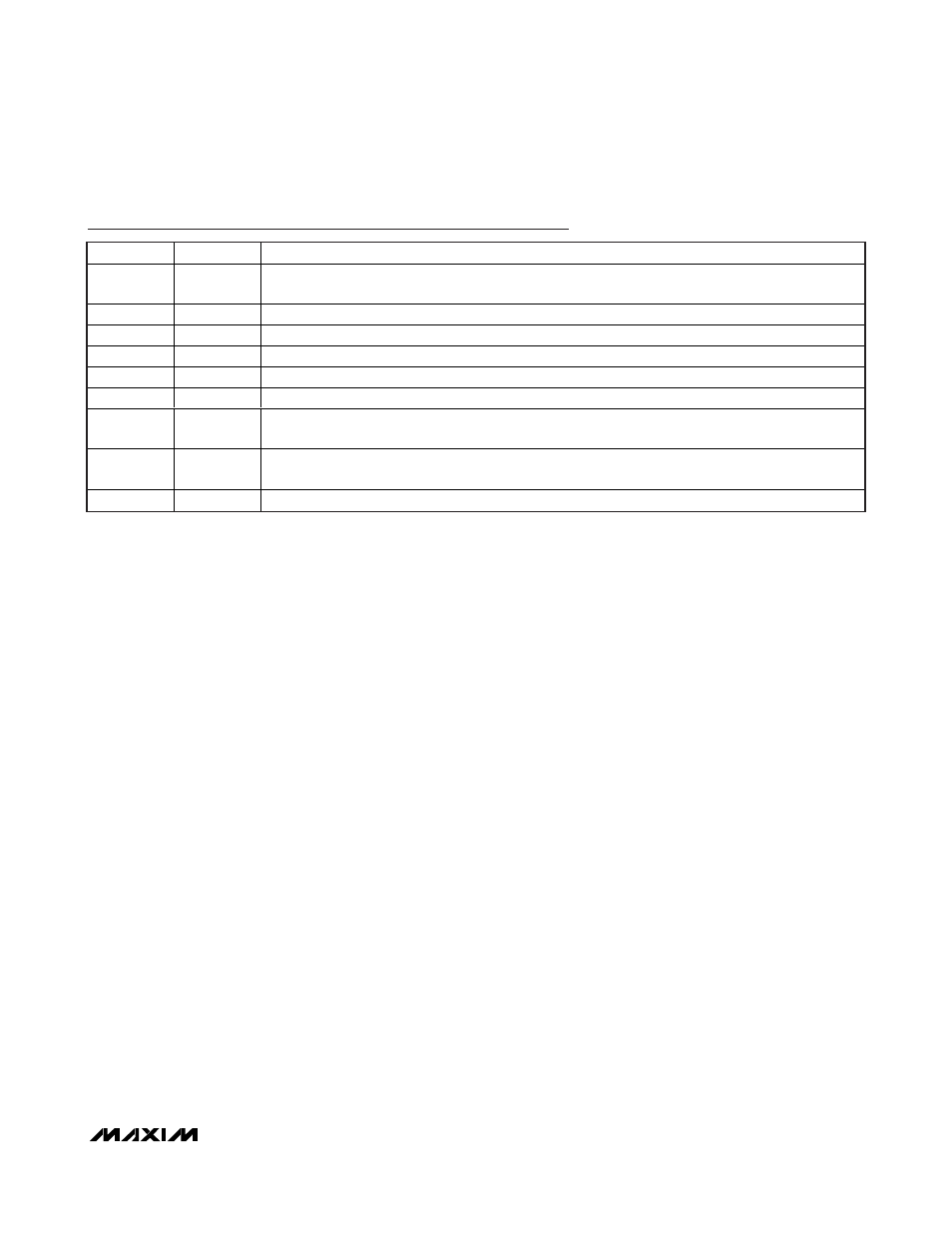
39
GND_TUNE
VTUNE Ground Connection. Connect to the PCB ground plane. All loop filter component GNDs must
be connected to this pin (see the Typical Application Circuit).
40
VTUNE
VCO Tuning Input. Connect to the PLL loop filter output.
42
MUX
Test Output. Leave this pin unconnected during normal operation.
43
CP
Charge-Pump Output. Connect to PLL loop filter input.
45
XTALN
Crystal Oscillator Feedback. See the Typical Application Circuit.
46
XTALP
Crystal Oscillator Feedback. See the Typical Application Circuit.
47
ADDR1
2-Wire Serial-Interface Address Line 1. This pin along with ADDR2 sets the device address for the
I
2
C-compatible serial interface.
48
ADDR2
2-Wire Serial-Interface Address Line 2. This pin along with ADDR1 sets the device address for the
I
2
C-compatible serial interface.
EP
GND
Exposed Paddle. Solder evenly to the PCB ground plane for proper operation.
Pin Description (continued)