Electrical characteristics (continued) – Rainbow Electronics MAX3941 User Manual
Page 3
MAX3941
10Gbps EAM Driver with Integrated
Bias Network
_______________________________________________________________________________________
3
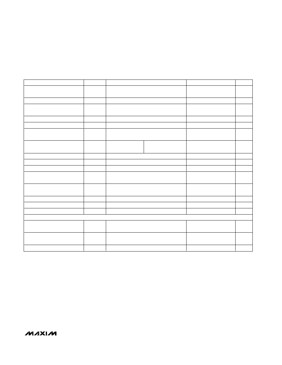
ELECTRICAL CHARACTERISTICS (continued)
(V
EE
= -5.5V to -4.9V, T
A
= -40°C to +85°C. Typical values are at V
EE
= -5.2V, I
BIAS
= 30mA, I
MOD
= 100mA, and T
A
= +25°C, unless
otherwise noted.)
PARAMETER
SYMBOL
CONDITIONS
MIN
TYP
MAX
UNITS
Modulation Set Bandwidth
Modulation depth 10%, 50
Ω driver load,
Figure 2
5
MHz
MODSET Input Resistance
20
k
Ω
Modulation-Current Temperature
Stability
(Note 6)
-957
0
ppm/
°C
Modulation-Current-Setting Error
50
Ω driver load, T
A
= +25
°C
-10
+10
%
Output Resistance
R
OUT
OUT to GND
42.5
50
58.5
Ω
Total Off Current
BIASSET = V
EE
,
MODEN = V
EE
, MODSET =
V
EE
, DATA+ = high, DATA- = low
1.2
mA
Output Return Loss
RL
OUT
I
BIAS
= 30mA,
I
MOD
= 50mA
≤15GHz
10
dB
Output Edge Speed
20% to 80% (Notes 6, 8)
23
32
ps
Setup/Hold Time
t
SU
, t
HD
Figure 3 (Note 6)
25
ps
Pulse-Width Adjustment Range
(Notes 6, 8)
±30
±50
ps
Pulse-Width Control Input Range
(Single Ended)
For PWC+ and PWC-
V
EE
+
0.5
V
EE
+
1.5
V
Pulse-Width Control Input Range
(Differential)
(PWC+) - (PWC-)
-0.5
+0.5
V
Output Overshoot
δ
(Notes 6, 8)
10
%
Driver Random Jitter
RJ
DR
(Note 6)
0.3
0.7
ps
RMS
Driver Deterministic Jitter
DJ
DR
PWC- = GND (Notes 6, 9)
6.8
11
ps
P-P
CONTROL INPUTS
Input High Voltage
V
IH
(Note 10)
V
EE
+
2.0
V
Input Low Voltage
V
IL
(Note 10)
V
EE
+
0.8
V
Input Current
(Note 10)
-80
+200
µA
Note 1: Supply current remains elevated once the retiming function is enabled. Power must be cycled to reduce supply
current after the retiming function is disabled.
Note 2: Power-supply noise rejection is specified as PSNR = 20log(V
noise (on Vcc)
/
∆V
OUT
). V
OUT
is the voltage across a 50
Ω load.
V
noise (on Vcc)
= 100mV
P-P
.
Note 3: For DATA+, DATA-, CLK+, and CLK-.
Note 4: CLK input characterized at 10.7Gbps.
Note 5: R
BSEQV
= (V
BIASSET
- V
EE
) / I
BIAS
with MODEN = V
EE
, DATA+ = high, and DATA- = low.
Note 6: Guaranteed by design and characterization using the circuit shown in Figure 4.
Note 7: R
MODEQV
= (V
MODSET
- V
EE
) / (I
MOD
- 37mA) with BIASSET = V
EE
.
Note 8: 50
Ω load, characterized at 10.7Gbps with a 1111 1111 0000 0000 pattern.
Note 9: Deterministic jitter is defined as the arithmetic sum of pulse-width distortion (PWD) and pattern-dependent jitter (PDJ).
Measured with a 10.7Gbps 2
7
- 1 PRBS pattern with eighty 0s and eighty 1s inserted in the data pattern.
Note 10: For MODEN and PLRT.