Max3941, 10gbps eam driver with integrated bias network, Interface schematics – Rainbow Electronics MAX3941 User Manual
Page 10: Exposed-pad package, Laser safety and iec 825
MAX3941
Interface Schematics
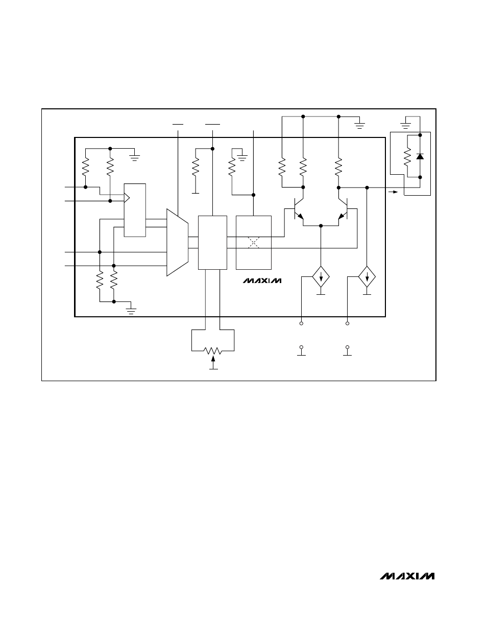
Figures 7 and 8 show simplified input and output cir-
cuits of the MAX3941 EAM driver.
Exposed-Pad Package
The exposed pad on the 24-pin QFN provides a very low
thermal-resistance path for heat removal from the IC. The
pad is also electrically ground on the MAX3941 and must
be soldered to the circuit board for proper thermal and
electrical performance. Refer to Maxim Application Note
HFAN-08.1: Thermal Considerations for QFN and Other
Exposed-Pad Packages for additional Information.
Laser Safety and IEC 825
Using the MAX3941 EAM driver alone does not ensure
that a transmitter design is compliant with IEC 825. The
entire transmitter circuit and component selections must
be considered. Each customer must determine the level
of fault tolerance required by their application, recogniz-
ing that Maxim products are not designed or authorized
for use as components in systems intended for surgical
implant into the body, for applications intended to sup-
port or sustain life, or for any other application where the
failure of a Maxim product could create a situation where
personal injury or death may occur.
10Gbps EAM Driver with Integrated
Bias Network
10
______________________________________________________________________________________
Figure 6. Functional Diagram
POLARITY
MAX3941
50
Ω
50
Ω
V
EE
V
EE
V
EE
50
Ω
50
Ω
50
Ω
R
OUT
50
Ω
50
Ω
50
Ω
D
0
1
Q
MUX
RTEN
MODEN
PLRT
GND
GND1
GND2
PWC
I
MOD
MODSET
+
V
MODSET
-
V
EE
V
EE
V
EE
I
BIAS
BIASSET
+
V
BIASSET
-
OUT
PWC+
PWC-
2k
Ω
CLK+
CLK-
DATA+
DATA-
Z
L